SPI Slave Configuration for the LPC1549 ( LPC15xx )

cancel
Showing results for 
Show  only  | Search instead for 
Did you mean: 

SPI Slave Configuration for the LPC1549 ( LPC15xx )

1,278 Views
vmaslov
Contributor I

I'm currently evaluating the SPI slave functionality of the LPC1549.

I'm wondering if there is any examples not using the ROM API, I'd like to be able to tweak the ISR to my liking and have more control on what's being transmitted.

Is there a data rate limit?


It seems like a feature that even the user guide lacks proper explanation and configuration of this state for the peripheral.

Currently I have the following configurations using LPCOPEN  :


for this example I'm using SPI0

 - Set GPIO direction for general SPI and a CS 

- Set the SWM settings corresponding to the proper PINASSIGN banks for SWM_SPI0_MOSI_IO, SWM_SPI0_SCK_IO, and SWM_SPI0_MISO_IO

- I then set the CS the same as if I were to be in Master mode ( Except CS is set to input ).

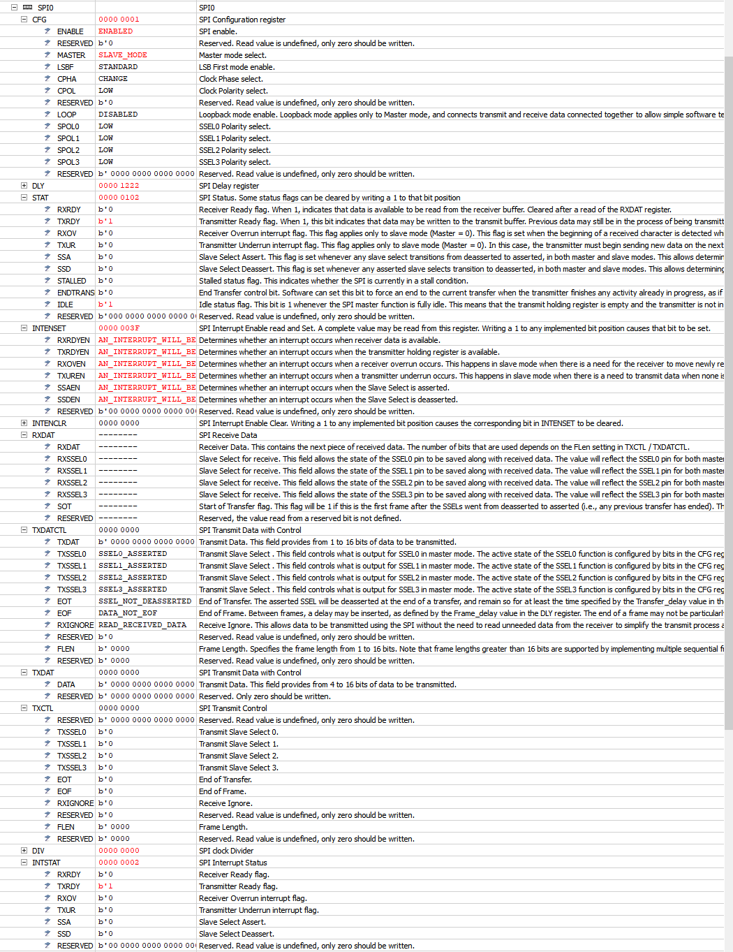
After initialization , the following configurations are set in the SPI0 peripheral register : 

spi_register.PNG

Once I send the following capture, The SSA ( Slave Select Assert ) and SSD ( Deassert ) are found to be set, but I would expect the RXRDY to be set as well.

Capture.PNG

Let me know if you guys require additional information, I'd love to chat about this!

Victor

Labels (2)
Tags (1)
3 Replies

914 Views
Alice_Yang
NXP TechSupport
NXP TechSupport

Hello Victor Maslov,

It seems there isn't SPI slave demo about LPC1549 under LPCopen.

Could you please show your code ?

BR

Alice

0 Kudos

914 Views
vmaslov
Contributor I

This morning, I've decide to try the ROM polling example.

I'm currently using the ROM example as provided, using 8 bit instead of 16 bit transfer, and only 1 byte for my receive side.

I'm sending the same byte from the snippet above.


Here are the two lines I've modified to work with the 8 bit 1 byte "message"

#define SPI_RX_BUFFER_SIZE 1

paramRec.fsize_sel = 0x07000000;/* Set Tx Control for 8 bit transfer, SSEL doesn't matter */

I'd like to reinstate that I find it odd the lack of documentation on slave mode for the LPC15xx devices. Is there any documentation with additional descriptions on it's functionality & configuration?


/*
* @brief SPI bus slave example using the ROM API in polling mode
*
* @note
* Copyright(C) NXP Semiconductors, 2014
* All rights reserved.
*
* @par
* Software that is described herein is for illustrative purposes only
* which provides customers with programming information regarding the
* LPC products. This software is supplied "AS IS" without any warranties of
* any kind, and NXP Semiconductors and its licensor disclaim any and
* all warranties, express or implied, including all implied warranties of
* merchantability, fitness for a particular purpose and non-infringement of
* intellectual property rights. NXP Semiconductors assumes no responsibility
* or liability for the use of the software, conveys no license or rights under any
* patent, copyright, mask work right, or any other intellectual property rights in
* or to any products. NXP Semiconductors reserves the right to make changes
* in the software without notification. NXP Semiconductors also makes no
* representation or warranty that such application will be suitable for the
* specified use without further testing or modification.
*
* @par
* Permission to use, copy, modify, and distribute this software and its
* documentation is hereby granted, under NXP Semiconductors' and its
* licensor's relevant copyrights in the software, without fee, provided that it
* is used in conjunction with NXP Semiconductors microcontrollers. This
* copyright, permission, and disclaimer notice must appear in all copies of
* this code.
*/

#include "board.h"

/*****************************************************************************
* Private types/enumerations/variables
****************************************************************************/

#define SPI_RX_BUFFER_SIZE 1
/* SPI slave handle and memory for ROM API */
static SPI_HANDLE_T *spiHandleSlave;

/* Use a buffer size larger than the expected return value of
spi_get_mem_size() for the static SPI handle type */
static uint32_t spiSlaveHandleMEM[0x20];
/* Receive Buffer for SPI */
static uint16_t rx_buff[SPI_RX_BUFFER_SIZE];

/*****************************************************************************
* Public types/enumerations/variables
****************************************************************************/

/*****************************************************************************
* Private functions
****************************************************************************/

/* Initializes pin muxing for SPI interface - note that SystemInit() may
already setup your pin muxing at system startup */
static void Init_SPI_PinMux(void)
{
#if (defined(BOARD_NXP_LPCXPRESSO_1549))
    /* Enable the clock to the Switch Matrix */
    Chip_Clock_EnablePeriphClock(SYSCTL_CLOCK_SWM);
    /*
     * Initialize SPI0 pins connect
     * SCK0: PINASSIGN3[15:8]: Select P0.0
     * MOSI0: PINASSIGN3[23:16]: Select P0.16
     * MISO0: PINASSIGN3[31:24] : Select P0.10
     * SSEL0: PINASSIGN4[7:0]: Select P0.9
     */
    Chip_IOCON_PinMuxSet(LPC_IOCON, 0, 0, (IOCON_MODE_INACT | IOCON_DIGMODE_EN));
    Chip_IOCON_PinMuxSet(LPC_IOCON, 0, 16, (IOCON_MODE_INACT | IOCON_DIGMODE_EN));
    Chip_IOCON_PinMuxSet(LPC_IOCON, 0, 10, (IOCON_MODE_INACT | IOCON_DIGMODE_EN));
    Chip_IOCON_PinMuxSet(LPC_IOCON, 0, 9, (IOCON_MODE_INACT | IOCON_DIGMODE_EN));

    Chip_SWM_MovablePinAssign(SWM_SPI0_SCK_IO, 0);  /* P0.0 */
    Chip_SWM_MovablePinAssign(SWM_SPI0_MOSI_IO, 16);/* P0.16 */
    Chip_SWM_MovablePinAssign(SWM_SPI0_MISO_IO, 10);/* P0.10 */
    Chip_SWM_MovablePinAssign(SWM_SPI0_SSELSN_0_IO, 9); /* P0.9 */

    /* Disable the clock to the Switch Matrix to save power */
    Chip_Clock_DisablePeriphClock(SYSCTL_CLOCK_SWM);
#else
    /* Configure your own SPI pin muxing here if needed */
#warning "No SPI pin muxing defined"
#endif
}

/* Turn on LED to indicate an error */
static void errorSPI(void)
{
    Board_LED_Set(0, true);
    while (1) {}
}

/* Setup SPI handle and parameters */
static void setupSpiSlave()
{
    SPI_CONFIG_T spiConfigRec;

    /* Enable SPI clock and reset SPI peripheral - the boot ROM does not
     do this */
    Chip_SPI_Init(LPC_SPI0);

    /* Perform a sanity check on the storage allocation */
    if (LPC_SPID_API->spi_get_mem_size() > sizeof(spiSlaveHandleMEM)) {
        /* Example only: this should never happen and probably isn't needed for
         most SPI code. */
        errorSPI();
    }

    /* Setup the SPI0 handle */
    spiHandleSlave = LPC_SPID_API->spi_setup(LPC_SPI0_BASE, (uint8_t *) &spiSlaveHandleMEM);
    if (spiHandleSlave == NULL) {
        errorSPI();
    }
    /* Setup SPI0 configuration record */
    /* Delay doesn't matter for slave it is not used */
    spiConfigRec.delay = 0;
    /* SysClock divider is not used for slave */
    spiConfigRec.divider = 0;
    /* slave mode and SPI block enabled */
    spiConfigRec.config = 0x01;
    spiConfigRec.error_en = 0;

    /* Init SPI0 */
    LPC_SPID_API->spi_init(spiHandleSlave, &spiConfigRec);
}

/* Slave SPI Receive in interrupt mode */
static void ReadSpiMssg(uint16_t *xferPtr, uint32_t xferSize)
{
    SPI_PARAM_T paramRec;

    paramRec.tx_buffer = NULL;  /* SPI TX buffer */
    paramRec.size = xferSize;       /* total number of SPI transfers */
    paramRec.rx_buffer = xferPtr;   /* SPI RX buffer */
    paramRec.fsize_sel = 0x07000000;/* Set Tx Control for 8 bit transfer, SSEL doesn't matter */
    paramRec.eof_flag = 0;  /* End of Frame doesn't matter for slave */
    paramRec.tx_rx_flag = 1;        /* Receive only */
    paramRec.driver_mode = 0;       /* polling mode */
    paramRec.dma_cfg = NULL;        /* DMA configuration */
    paramRec.cb = NULL; /* SPI completion callback */
    paramRec.dma_cb = NULL;         /* DMA completion callback */

    /* Transfer message as SPI slave via polling */
    if (LPC_SPID_API->spi_slave_transfer(spiHandleSlave, &paramRec) != LPC_OK) {
        /* Signal SPI error */
        errorSPI();
    }
}

/*****************************************************************************
* Public functions
****************************************************************************/

/**
* @brief   Main routine for SPI example
* @return  Function should not exit
*/
int main(void)
{
    uint8_t i;
    /* Generic Initialization */
    SystemCoreClockUpdate();
    Board_Init();

    /* Clear activity LED */
    Board_LED_Set(0, false);

    /* Setup SPI pin muxing */
    Init_SPI_PinMux();

    /* Allocate SPI handle, setup rate, and initialize clocking */
    setupSpiSlave();

    /* Loop forever */
    while (1) {
        /* Read simple message over SPI */
        ReadSpiMssg(rx_buff, 1);
        for (i = 0; i < 1; i++) {
            DEBUGOUT("SPI Read Data %d is %x\r\n", i, rx_buff[i]);
        }

        /* Toggle LED to show activity. */
        Board_LED_Toggle(0);
    }

    /* Code never reaches here. Only used to satisfy standard main() */
    return 0;
}
0 Kudos

914 Views
Alice_Yang
NXP TechSupport
NXP TechSupport

Hello Victor ,

Sorry there isn't any other documents, only User Manual and the demo.

You can combine the Demo with "Chapter 39: LPC15xx SPI API ROM driver routines"

and "25.6 Register description" to config.


Have a great day,
TIC

-------------------------------------------------------------------------------
Note:
- If this post answers your question, please click the "Mark Correct" button. Thank you!

- We are following threads for 7 weeks after the last post, later replies are ignored
Please open a new thread and refer to the closed one, if you have a related question at a later point in time.
-------------------------------------------------------------------------------

0 Kudos