
- NXP Forums
- Product Forums
- General Purpose MicrocontrollersGeneral Purpose Microcontrollers
- i.MX Forumsi.MX Forums
- QorIQ Processing PlatformsQorIQ Processing Platforms
- Identification and SecurityIdentification and Security
- Power ManagementPower Management
- MCX Microcontrollers
- S32G
- S32K
- S32V
- MPC5xxx
- Other NXP Products
- Wireless Connectivity
- S12 / MagniV Microcontrollers
- Powertrain and Electrification Analog Drivers
- Sensors
- Vybrid Processors
- Digital Signal Controllers
- 8-bit Microcontrollers
- ColdFire/68K Microcontrollers and Processors
- PowerQUICC Processors
- OSBDM and TBDML
-
- Solution Forums
- Software Forums
- MCUXpresso Software and ToolsMCUXpresso Software and Tools
- CodeWarriorCodeWarrior
- MQX Software SolutionsMQX Software Solutions
- Model-Based Design Toolbox (MBDT)Model-Based Design Toolbox (MBDT)
- FreeMASTER
- eIQ Machine Learning Software
- Embedded Software and Tools Clinic
- S32 SDK
- S32 Design Studio
- GUI Guider
- Zephyr Project
- Voice Technology
- Application Software Packs
- Secure Provisioning SDK (SPSDK)
- Processor Expert Software
- MCUXpresso Training Hub
-
- Topics
- Mobile Robotics - Drones and RoversMobile Robotics - Drones and Rovers
- NXP Training ContentNXP Training Content
- University ProgramsUniversity Programs
- Rapid IoT
- NXP Designs
- SafeAssure-Community
- OSS Security & Maintenance
- Using Our Community
-
- Cloud Lab Forums
-
- Home
- :
- i.MX Forums
- :
- i.MX RT
- :
- UART6 serial output not working in demo app [iMX RT106S/SLN-LOCAL2-IOT]
UART6 serial output not working in demo app [iMX RT106S/SLN-LOCAL2-IOT]
- Subscribe to RSS Feed
- Mark Topic as New
- Mark Topic as Read
- Float this Topic for Current User
- Bookmark
- Subscribe
- Mute
- Printer Friendly Page
UART6 serial output not working in demo app [iMX RT106S/SLN-LOCAL2-IOT]
- Mark as New
- Bookmark
- Subscribe
- Mute
- Subscribe to RSS Feed
- Permalink
- Report Inappropriate Content
I have an iMX RT106S board from SLN-LOCAL2-IOT for speech recognition and I need activatd UART6 serial output for commands recognized.
I did a BOARD_InitDebugConsole() in main() function of demo app but whether with configPRINTF or PRINTF macro no serial output gets written to UART6 serial output.
T tried several macros, e.g.
SDK_DEBUGCONSOLE=0
BOARD_USEVIRTUALCOM=1
SERIAL_PORT_TYPE_USBCDC=1
DEBUG_CONSOLE_RX_ENABLE=0
SERIAL_PORT_TYPE_UART=1
but no change with these preprocessor settings.
I can verify that serial output is working regarding hardware as I get some output from BOOTLOADER code running before demo app, so I suspect it is a software issue
Thanks for any help
- Mark as New
- Bookmark
- Subscribe
- Mute
- Subscribe to RSS Feed
- Permalink
- Report Inappropriate Content
Hi Kerry,
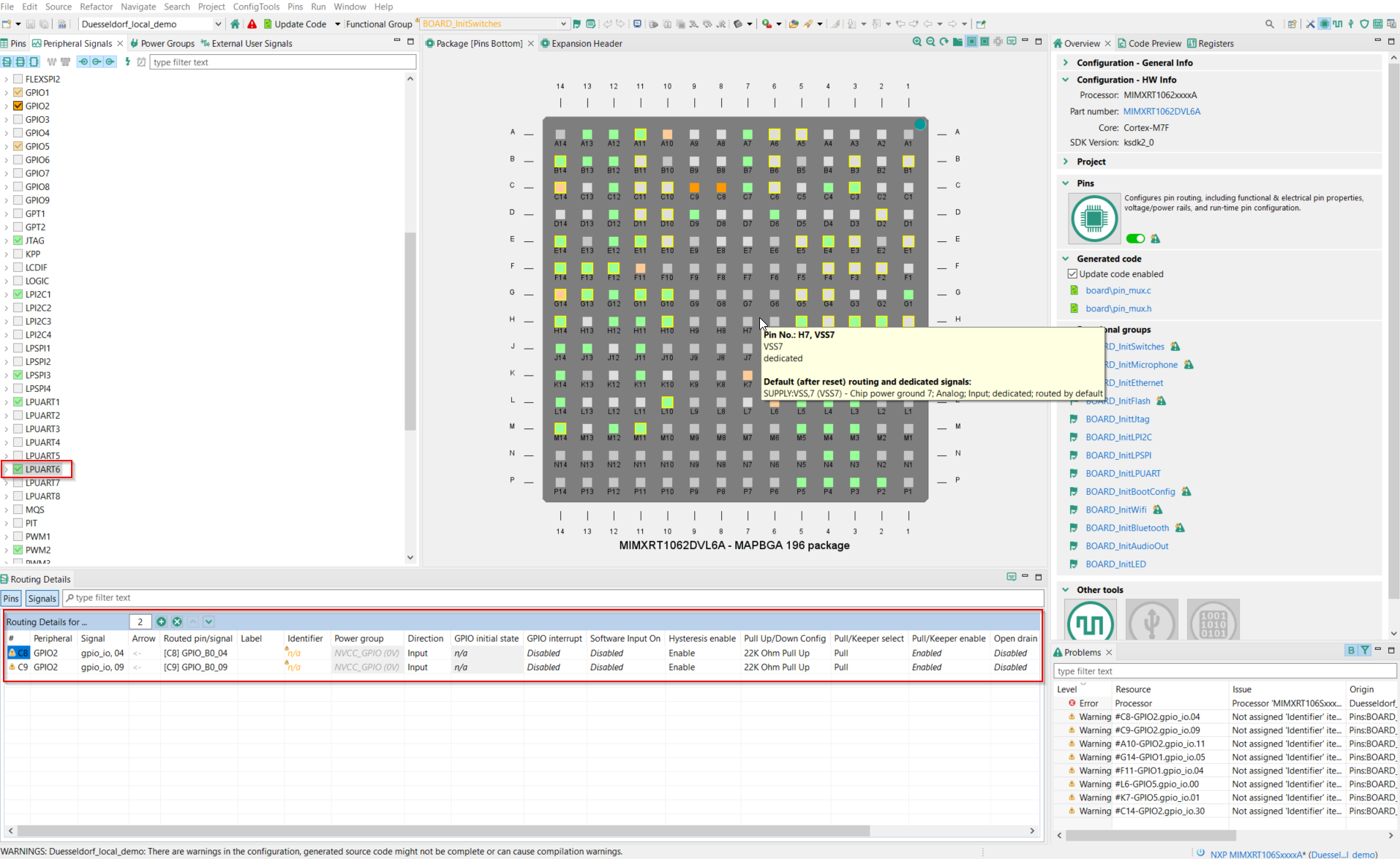
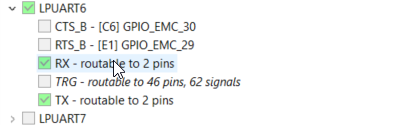
thanks for your answer. As I am beginner with MCUXpresso IDE & NXP boards, could you provide me some pointers how to check use of correct pins in project? I can see in pins configuration that LPUART6 seems to be activated (see attached screenshot)
What do you mean that bootloader can access UART6 directy? I importec the project from demo project and it worked some time ago so I don't think that it is a hardware configuration issue.
Thanks for any help,
Best Regards,
Lorky
- Mark as New
- Bookmark
- Subscribe
- Mute
- Subscribe to RSS Feed
- Permalink
- Report Inappropriate Content
Hi @lorky ,
Welcome to use our NXP local2 board!
From your picture, seems you are using the wrong pin, please check the schematic:

Please double check your hardware and software, make sure it is matched.
Which SDK code you are using now? You need to use SDK_2_8_0_SLN-LOCAL2-IOT.zip, this code can make the UART6 works directly when you connect the :

Wish it helps you!
Best Regards,
kerry
- Mark as New
- Bookmark
- Subscribe
- Mute
- Subscribe to RSS Feed
- Permalink
- Report Inappropriate Content
Hi Kerry,
thank you for your help!
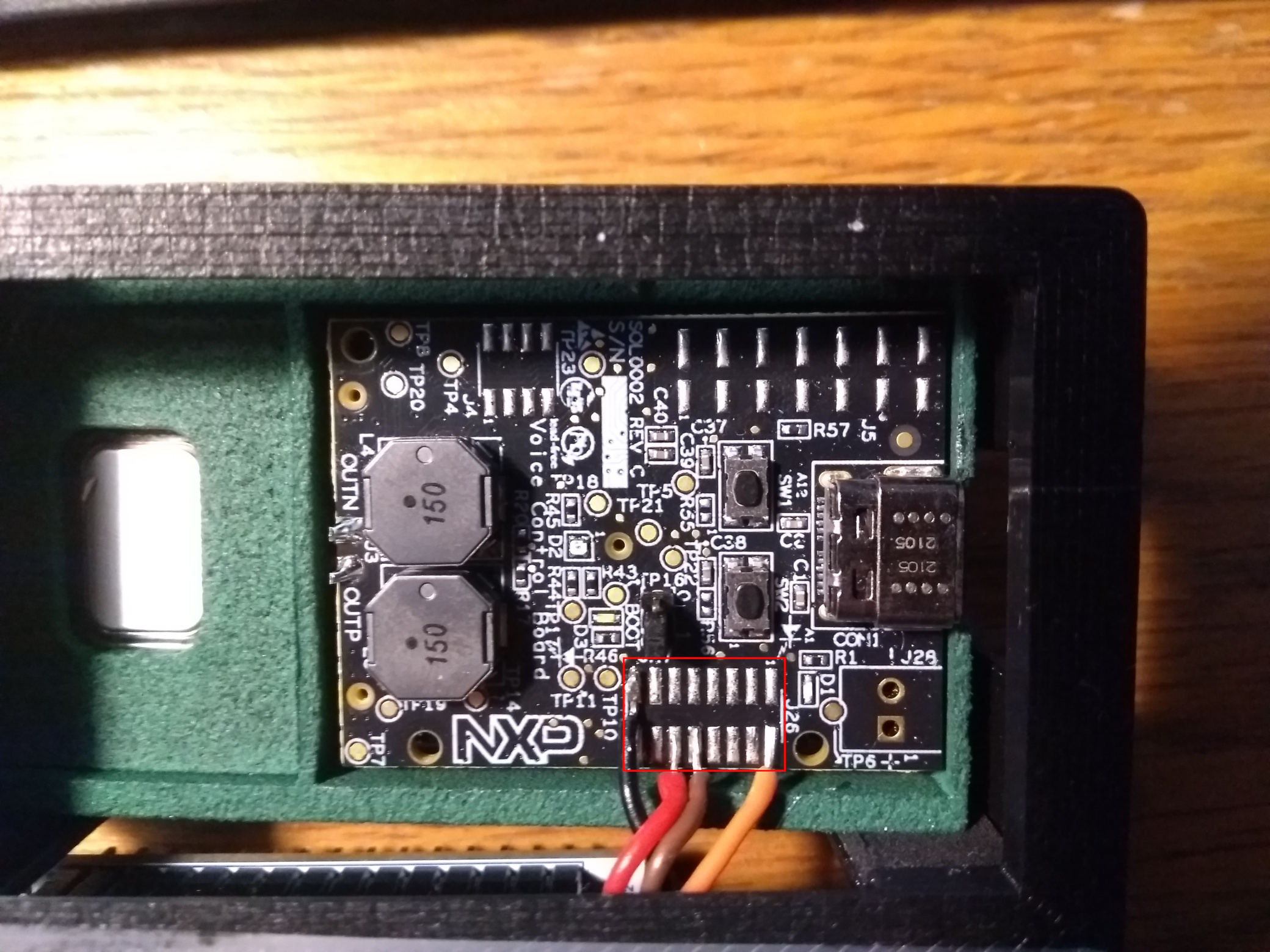
I checked J26 pin header with my board, please see attached picture.
If I understand correctly, in my case pins are soldered correctly with pin10 (brown) and pin12 (red).
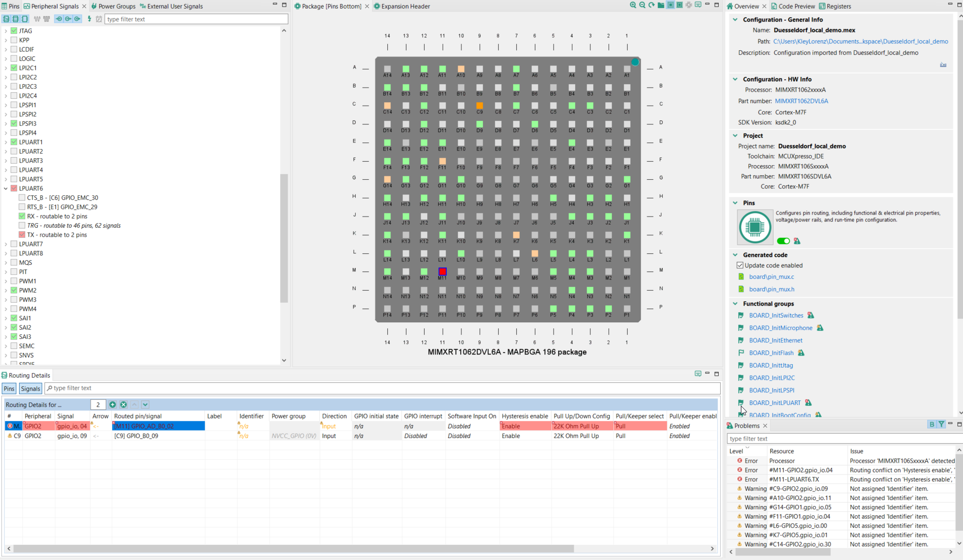
But I cannot map LPUART6 to GPIO_AD_B0_02 and GPIO_AD_B0_03, software giving an error (Routed pin/signal is greyed out) (please see attached screenshot).
Furthermore I imported sln_local2_iot_bootloader project directly from SDK and there the same configuration (with GPIO_B0_04 and GPIO_B0_09) is used and serial output with LPUART6 is working with bootloader.
I am using SDK_2.x_SLN-LOCAL2-IOT SDK version 2.8.0 and project is directly imported from sln_local2_iot_local_demo.
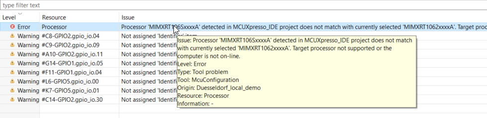
I checked software configuration and observed an error stating that processor type does not match (see last attachment)
Thanks for any help,
Best Regards,
Lorky
- Mark as New
- Bookmark
- Subscribe
- Mute
- Subscribe to RSS Feed
- Permalink
- Report Inappropriate Content
Hi @lorky ,
You don't need to configure the code by yourself, please don't do it.
As the SDK code already contains the code, you can delete all the local2 code at first, then import it again, as if you configure it, you may destroy some other function.
Please check the bootloader:
void BOARD_InitLPUART(void) {
  CLOCK_EnableClock(kCLOCK_Iomuxc);           /* iomuxc clock (iomuxc_clk_enable): 0x03U */

  IOMUXC_SetPinMux(
      IOMUXC_GPIO_AD_B0_02_LPUART6_TX,        /* GPIO_AD_B0_02 is configured as LPUART6_TX */
      0U);                                    /* Software Input On Field: Input Path is determined by functionality */
  IOMUXC_SetPinMux(
      IOMUXC_GPIO_AD_B0_03_LPUART6_RX,        /* GPIO_AD_B0_03 is configured as LPUART6_RX */
      0U);                                    /* Software Input On Field: Input Path is determined by functionality */
  IOMUXC_SetPinConfig(
      IOMUXC_GPIO_AD_B0_02_LPUART6_TX,        /* GPIO_AD_B0_02 PAD functional properties : */
      0x10B0U);                               /* Slew Rate Field: Slow Slew Rate
                                                 Drive Strength Field: R0/6
                                                 Speed Field: medium(100MHz)
                                                 Open Drain Enable Field: Open Drain Disabled
                                                 Pull / Keep Enable Field: Pull/Keeper Enabled
                                                 Pull / Keep Select Field: Keeper
                                                 Pull Up / Down Config. Field: 100K Ohm Pull Down
                                                 Hyst. Enable Field: Hysteresis Disabled */
  IOMUXC_SetPinConfig(
      IOMUXC_GPIO_AD_B0_03_LPUART6_RX,        /* GPIO_AD_B0_03 PAD functional properties : */
      0x10B0U);                               /* Slew Rate Field: Slow Slew Rate
                                                 Drive Strength Field: R0/6
                                                 Speed Field: medium(100MHz)
                                                 Open Drain Enable Field: Open Drain Disabled
                                                 Pull / Keep Enable Field: Pull/Keeper Enabled
                                                 Pull / Keep Select Field: Keeper
                                                 Pull Up / Down Config. Field: 100K Ohm Pull Down
                                                 Hyst. Enable Field: Hysteresis Disabled */
}
void BOARD_InitDebugConsole(void)
{
    uint32_t uartClkSrcFreq = BOARD_DebugConsoleSrcFreq();

    DbgConsole_Init(BOARD_DEBUG_UART_INSTANCE, BOARD_DEBUG_UART_BAUDRATE, BOARD_DEBUG_UART_TYPE, uartClkSrcFreq);
}
Then you can use the following code to do printf:
configPRINTF(("SYSTEM_Init\r\n"));
Wish it helps you!
Best Regards,
kerry
- Mark as New
- Bookmark
- Subscribe
- Mute
- Subscribe to RSS Feed
- Permalink
- Report Inappropriate Content
Hi @kerryzhou ,
thank you for your answer. I did not configure the code by myself, just checked that pin configuration is the same for bootloader and demo_app projects so I suppose this is correct as I get output from bootloader.
I checked the code you mentioned (BOARD_InitLPUART() function) and the functions is the same as you posted, GPIO pins for TX/RX correctly configured, and also BOARD_InitDebugConsole correctly initializing UART6
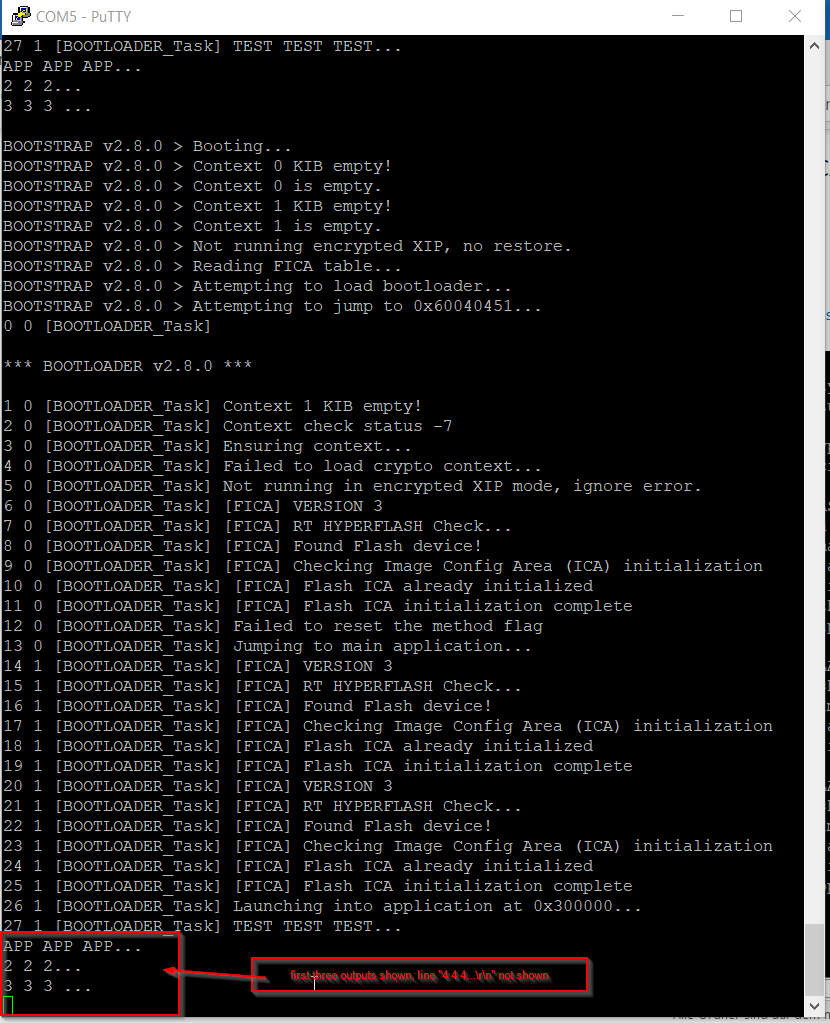
But I did manage finally to get some output on serial LPUART6 from demo app finally, event if it is not the whole output I expect.
I did some PRINTF() outputs in local_voice_task() from beginning down and some time while executing the function, serial output stops and no further output is seen on console. In the attached code the output stops between PRINTF("3 3 3...\r\n"); and PRINTF("4 4 4 ...\r\n"); lines.
I really have no idea why this happens, is there some buffer one has to consider for serial output? Why does it work at the beginning of the task but not further down the line?
Thanks for any pointers or suggestions,
Best Regards,
Lorky
- Mark as New
- Bookmark
- Subscribe
- Mute
- Subscribe to RSS Feed
- Permalink
- Report Inappropriate Content
Hi @lorky ,
You don't need to check the CFG pin situation, as the project is use the code to configure it, not the CFG tool, so, just check the source code is enough.
I think your code is caused by the code.
You can try to move the :
PRINTF("4 4 4 ... \r\n");
above :
while (!g_xSampleQueue)
vTaskDelay(10);

Whether it works or not?
If it works, then it means, your code is looping in: while (!g_xSampleQueue)
You need to check your code details.
Until now, I believe your UART6 already works.
If you have any other function issues, please help to create the new case, as normally, one case to one question topic, thanks.
Best Regards,
kerry
- Mark as New
- Bookmark
- Subscribe
- Mute
- Subscribe to RSS Feed
- Permalink
- Report Inappropriate Content
Hi @lorky ,
Which detail pin you are using in the SLN-LOCAL2-IOT for the UART6?
I have written a chinese document which is using the UART6, you can check it at first with the translation tool.
You need to use the correct pin, in the J26 pin 10, pin12,:
TTL USB UART_TX <->UART6_RX J26_10
TTL USB UART_ R X <->UART6_ T X J26_ 2 0
TTLUSB GND GND <-> J26_15
In fact, the bootloader can support the UART6 directly, at least, I have tested in the previous time.
Please refer to my doc to check it again. I use it to release the OTW function.
Wish it helps you!
Best Regards,
Kerry