
- NXP Forums
- Product Forums
- General Purpose MicrocontrollersGeneral Purpose Microcontrollers
- i.MX Forumsi.MX Forums
- QorIQ Processing PlatformsQorIQ Processing Platforms
- Identification and SecurityIdentification and Security
- Power ManagementPower Management
- MCX Microcontrollers
- S32G
- S32K
- S32V
- MPC5xxx
- Other NXP Products
- Wireless Connectivity
- S12 / MagniV Microcontrollers
- Powertrain and Electrification Analog Drivers
- Sensors
- Vybrid Processors
- Digital Signal Controllers
- 8-bit Microcontrollers
- ColdFire/68K Microcontrollers and Processors
- PowerQUICC Processors
- OSBDM and TBDML
-
- Solution Forums
- Software Forums
- MCUXpresso Software and ToolsMCUXpresso Software and Tools
- CodeWarriorCodeWarrior
- MQX Software SolutionsMQX Software Solutions
- Model-Based Design Toolbox (MBDT)Model-Based Design Toolbox (MBDT)
- FreeMASTER
- eIQ Machine Learning Software
- Embedded Software and Tools Clinic
- S32 SDK
- S32 Design Studio
- Vigiles
- GUI Guider
- Zephyr Project
- Voice Technology
- Application Software Packs
- Secure Provisioning SDK (SPSDK)
- Processor Expert Software
-
- Topics
- Mobile Robotics - Drones and RoversMobile Robotics - Drones and Rovers
- NXP Training ContentNXP Training Content
- University ProgramsUniversity Programs
- Rapid IoT
- NXP Designs
- SafeAssure-Community
- OSS Security & Maintenance
- Using Our Community
-
- Cloud Lab Forums
-
Hi,
I've recieved i.MX53 QSB and I would like to embed OmniVision sensor to it. As I understand an expansion header supports CSI camera to be connected and there is a standart board-to-board connector for expansion header. But I don't know about camera boards that supports such connector.
So, is there any camera boards with OmniVision or other image sensors for i.MX53 QSB? If not, what I need to do to embed camera to QSB?
Thanks in advance for any answer,
Alexander
已解决! 转到解答。
Thanks!
Will try like scheme below:
OV7620's pins - Exp. header's pins
1 - 59
2 - 24
3 - 29
4 - 3
5 - 31
6 - 33
7 - 58
8 - 53
9 - 56
10 - 17
11 - 19
12 - 52
13 - 38
14 - 50
15 - 30
16 - 46
17 - 35
18 - 44
19 - 26
20 - 34
21 - 28
22 - 32
23 - 21 (No connect)
24 - 22 (No Connect)
But I am not sure about 1st and 6th sensor's pins.
In OV7670 datasheet says the following:
Pin Number Name Pin Type Function/Description
01 STRB Output LED/strobe control output
06 RESET # Function Chip reset, active low
(default = 1)
May be 6th pin should be maped to 59 IMX pin (CSI_RSTB) that is RESET pin as I undestand. But what to do with 1st sensor's pin in this case?
Please download the QSB schematic from the i.MX53QSB web page. In the page 13, there is a connector J13. The CSI0 signals are linked to this J13. You can make your adapter board with your camera and then connect it to this J13.
Thanks a lot! But what document do you mean?
May be http://cache.freescale.com/files/32bit/doc/user_guide/IMX53QSBRM.pdf?fpsp= ?
Thanks. This scheme is the same as in the document that mentionted by me.
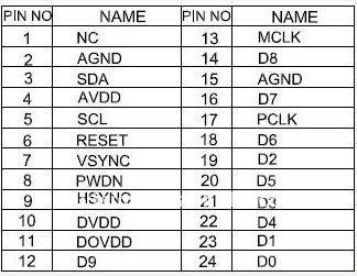
I have OmniVision sensor OV7670 with 24 pins described here http://i01.i.aliimg.com/img/pb/912/479/406/406479912_434.jpg. As I see it has 10 data pins that are D0 - D9. And I don't undestand how to map them to exp. header because I found only 8 data pins on scheme: CSI0_DAT12 - CSI0_DAT19.
As the exp. header only have CSI0_DAT12 - CSI0_DAT19, this only can support 8-bit mode. So please check the OV7670 datasheet. It should able to set to work in 10bit mode and 8bit mode. And the datasheet should show you which data pins are for 8bit.
Thanks!
Will try like scheme below:
OV7620's pins - Exp. header's pins
1 - 59
2 - 24
3 - 29
4 - 3
5 - 31
6 - 33
7 - 58
8 - 53
9 - 56
10 - 17
11 - 19
12 - 52
13 - 38
14 - 50
15 - 30
16 - 46
17 - 35
18 - 44
19 - 26
20 - 34
21 - 28
22 - 32
23 - 21 (No connect)
24 - 22 (No Connect)
But I am not sure about 1st and 6th sensor's pins.
In OV7670 datasheet says the following:
Pin Number Name Pin Type Function/Description
01 STRB Output LED/strobe control output
06 RESET # Function Chip reset, active low
(default = 1)
May be 6th pin should be maped to 59 IMX pin (CSI_RSTB) that is RESET pin as I undestand. But what to do with 1st sensor's pin in this case?
Is it a typo in your scheme? your scheme show pin 6 is to 33. the correct one should be 59?
For the STRB pin, I think the usage is depends on your application.
e.g. it can be used for triggering a flash. In the below AN, the Figure 10 is an example.
< http://www.skyworksinc.com/uploads/documents/AATI_AN_61.pdf >
It was my first opinion that pin 6 should be connected to pin 33. But it's not true and now I'm pretty sure that pin 6 is mapped to pin 59 on QSB.
I also suppose to keep pin 1 unconnected because I have no LED/Flash.
So, new scheme are here:
1 - 23 (No connect)
2 - 24
3 - 29
4 - 3
5 - 31
6 - 59
7 - 58
8 - 53
9 - 56
10 - 17
11 - 19
12 - 52
13 - 38
14 - 50
15 - 30
16 - 46
17 - 35
18 - 44
19 - 26
20 - 34
21 - 28
22 - 32
23 - 21 (No connect)
24 - 22 (No Connect)