
- NXP Forums
- Product Forums
- General Purpose MicrocontrollersGeneral Purpose Microcontrollers
- i.MX Forumsi.MX Forums
- QorIQ Processing PlatformsQorIQ Processing Platforms
- Identification and SecurityIdentification and Security
- Power ManagementPower Management
- MCX Microcontrollers
- S32G
- S32K
- S32V
- MPC5xxx
- Other NXP Products
- Wireless Connectivity
- S12 / MagniV Microcontrollers
- Powertrain and Electrification Analog Drivers
- Sensors
- Vybrid Processors
- Digital Signal Controllers
- 8-bit Microcontrollers
- ColdFire/68K Microcontrollers and Processors
- PowerQUICC Processors
- OSBDM and TBDML
-
- Solution Forums
- Software Forums
- MCUXpresso Software and ToolsMCUXpresso Software and Tools
- CodeWarriorCodeWarrior
- MQX Software SolutionsMQX Software Solutions
- Model-Based Design Toolbox (MBDT)Model-Based Design Toolbox (MBDT)
- FreeMASTER
- eIQ Machine Learning Software
- Embedded Software and Tools Clinic
- S32 SDK
- S32 Design Studio
- Vigiles
- GUI Guider
- Zephyr Project
- Voice Technology
- Application Software Packs
- Secure Provisioning SDK (SPSDK)
- Processor Expert Software
-
- Topics
- Mobile Robotics - Drones and RoversMobile Robotics - Drones and Rovers
- NXP Training ContentNXP Training Content
- University ProgramsUniversity Programs
- Rapid IoT
- NXP Designs
- SafeAssure-Community
- OSS Security & Maintenance
- Using Our Community
-
- Cloud Lab Forums
-
- Home
- :
- Product Forums
- :
- Wireless Connectivity
- :
- Custom KW38 PCB from ER-RD and FRDM
Custom KW38 PCB from ER-RD and FRDM
- Subscribe to RSS Feed
- Mark Topic as New
- Mark Topic as Read
- Float this Topic for Current User
- Bookmark
- Subscribe
- Mute
- Printer Friendly Page
- Mark as New
- Bookmark
- Subscribe
- Mute
- Subscribe to RSS Feed
- Permalink
- Report Inappropriate Content
Hello NXP,
We have designed our custom PCB for KW38 which is a small version of KW38-FRDM or KW38 ER-RD board.
However, we are not able to communicate with the chip through KW38_SWD_DIO/KW38_SWD_CLK/RST_TGTMCU_b signals. I have attached a pdf of the board schematic. Here are a few questions:
1) Pin #3, RST_TGTMCU_b is connected to a switch for reset. We did not use 10k pull up resistor or the 0.1uF cap for this pin. Is this a problem?
2) We want to communicate and program the chip via JTAG connector (H1 on the schematic).
Is programming of a new MKW38 chip with 2Wire JTAG passible? Or, do we need to have a special HW or a programmer to 1st program the chip before we assemble it on the board?
Thanks
Nader
Solved! Go to Solution.
- Mark as New
- Bookmark
- Subscribe
- Mute
- Subscribe to RSS Feed
- Permalink
- Report Inappropriate Content
Please see below:
- I would strongly suggest using the FRDM-KW38 Hardware design files (available on the Design Resources section from the FRDM-KW38 webpage) as a reference for your design.
- We already used them. Mainly ER-RD board.
- Also, could you please take a look at the Design Considerations for Debug? This article describes debug related signals and considerations for both JTAG and SWD.
- We need to read and apply these suggestions.
- You may also find the Hardware Design Considerations for MKW39A/38A/37A/38Z/37Z Bluetooth LE Devices helpful for your development.
- I believe we have already used this application note.
- According to the MKW39/38/37 Data Sheet, this device may only support Serial Wire Debug (SWD) Interface and Micro Trace buffer.
- I ordered this debugger which is based on 2pin SWD connections. Here is the LINK
On a separate note, I noticed in FRDM and ER-RD boards, the 32MHz XTAL does not have any parallel caps to the GND. My understanding is there should be external caps (usually in the range of 10-20pF) to make the XTAL oscillates. Is there any reason these is no caps between the XTAL and the GND. See below.

Cheers,
Nader
- Mark as New
- Bookmark
- Subscribe
- Mute
- Subscribe to RSS Feed
- Permalink
- Report Inappropriate Content
Hello @ArianRF
Hope you are doing well.
I would strongly suggest using the FRDM-KW38 Hardware design files (available on the Design Resources section from the FRDM-KW38 webpage) as a reference for your design.
Also, could you please take a look at the Design Considerations for Debug? This article describes debug related signals and considerations for both JTAG and SWD. You may also find the Hardware Design Considerations for MKW39A/38A/37A/38Z/37Z Bluetooth LE Devices helpful for your development.
According to the MKW39/38/37 Data Sheet, this device may only support Serial Wire Debug (SWD) Interface and Micro Trace buffer.
Regards,
Eduardo.
- Mark as New
- Bookmark
- Subscribe
- Mute
- Subscribe to RSS Feed
- Permalink
- Report Inappropriate Content
Please see below:
- I would strongly suggest using the FRDM-KW38 Hardware design files (available on the Design Resources section from the FRDM-KW38 webpage) as a reference for your design.
- We already used them. Mainly ER-RD board.
- Also, could you please take a look at the Design Considerations for Debug? This article describes debug related signals and considerations for both JTAG and SWD.
- We need to read and apply these suggestions.
- You may also find the Hardware Design Considerations for MKW39A/38A/37A/38Z/37Z Bluetooth LE Devices helpful for your development.
- I believe we have already used this application note.
- According to the MKW39/38/37 Data Sheet, this device may only support Serial Wire Debug (SWD) Interface and Micro Trace buffer.
- I ordered this debugger which is based on 2pin SWD connections. Here is the LINK
On a separate note, I noticed in FRDM and ER-RD boards, the 32MHz XTAL does not have any parallel caps to the GND. My understanding is there should be external caps (usually in the range of 10-20pF) to make the XTAL oscillates. Is there any reason these is no caps between the XTAL and the GND. See below.
Cheers,
Nader
- Mark as New
- Bookmark
- Subscribe
- Mute
- Subscribe to RSS Feed
- Permalink
- Report Inappropriate Content
Hi,
32 kHz oscillator module and 26MHZ/32MHz XTAL block should consist of internal feedback resistor and internal programmable capacitors as the CLOAD of the oscillator.
For more information on this, you can consult MKW39/38/37 Reference Manual, Chapter 28: 32kHz Oscillator and Section 46.14.2.1: XO Block.
Regards,
Eduardo.
- Mark as New
- Bookmark
- Subscribe
- Mute
- Subscribe to RSS Feed
- Permalink
- Report Inappropriate Content
+ @hgazeri
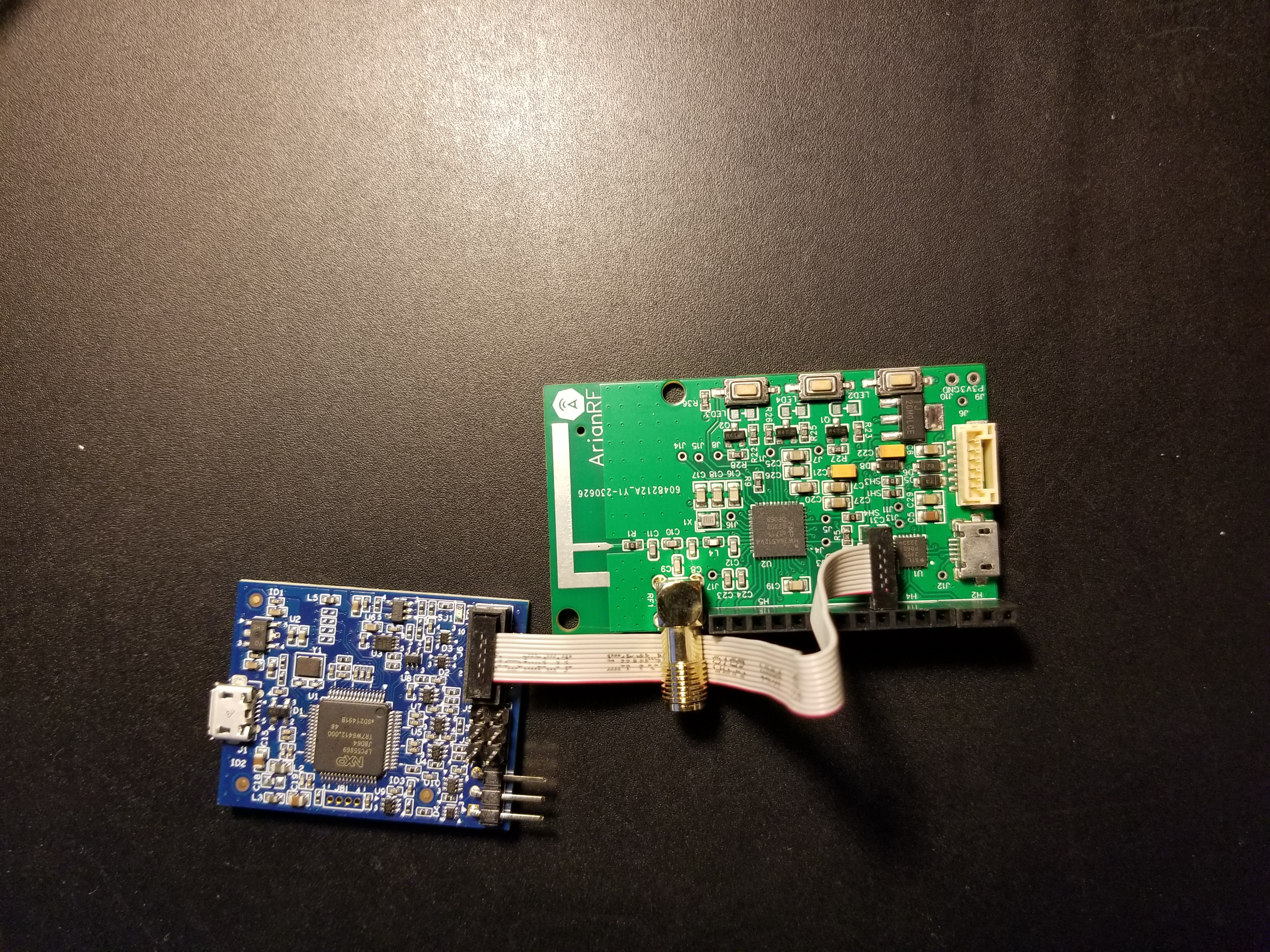
We applied the changes you suggested but still cannot talk to the chip. We are using NXP MCU-Link Debug Probe. Here are a few questions:
1) How can we enable pin 29, xtal_out to make sure we have a clock?
2) Can we use MCU-Link Debug Probe to talk to a fresh chip of the shelf? Does the boot ROM of the KW38 support it?
3) Our 32M xtal is not exactly the NX2016SA EXS00A-CS11775? It is a 32MHz 8pF (Q22FA12800025). Can this be a problem?
4) Can we use an external 32MHz to our KW38 from its Xtal pins? If yes, can you provide some information?
Please see the attached photos.
Regards
Nader
- Mark as New
- Bookmark
- Subscribe
- Mute
- Subscribe to RSS Feed
- Permalink
- Report Inappropriate Content
Hi,
I will recommend verifying that your XTAL is oscillating by using an oscilloscope. Also, it would be very helpful if you could check the SWD signals with a logic analyzer.
Have you seen the same behavior with another custom board of the same batch? Is it possible for you to reproduce this behavior with another of your custom boards?
Regards,
Eduardo.
- Mark as New
- Bookmark
- Subscribe
- Mute
- Subscribe to RSS Feed
- Permalink
- Report Inappropriate Content
+ @hgazeri
I don't see any osc using scope on the xtal pins. However, on the FRDM and ER-RD board can't see it either although those are working just fine.
A couple of observation:
1) The RST_TGTMCU_b (pin 3) on my board shows 0v despite having a 10k pull up resistor. On the FRDM board, I can see it is 3.3V. So this means the KW38 is in reset all the time, any idea why?
2) From KW38 document it says we need to set XTAL_OUT_EN = 1 to see XTAL_OUT signal (pin 29). How can we access XTAL_OUT_EN?
Appreciate your prompt response.
Cheers,
Nader
- Mark as New
- Bookmark
- Subscribe
- Mute
- Subscribe to RSS Feed
- Permalink
- Report Inappropriate Content
Hi,
Just to confirm, your device is using Bypass mode as DC-DC Power mode, is this correct?
Also, I would recommend checking the NMI pin state (pin 23/PTB18) and adding a pull-up resistor to this pin. This pin controls the Non Maskable Interrupt and leaving it unconnected may cause the MCU to keep resetting itself (NMI is active LOW).
To configure XTAL related registers, you may need to flash your device with an application that enables this feature.
Regards,
Eduardo.
- Mark as New
- Bookmark
- Subscribe
- Mute
- Subscribe to RSS Feed
- Permalink
- Report Inappropriate Content
+ Henry Gazeri & Iain Galloway
Thanks @EduardoZamora
Yes. It is in bypass mode and we use a regulator to generate a 3.3V supply from 5V (The supply is 3V indeed but I think that should be ok)
I pulled up pin23 (PTB18) by a 10k resistor. Still the chip is not operating. The RST_TGTMCU_b (pin 3) is still at 0V and there is no oscillation.
Can you please check our schematic and see if anything is fundamentally wrong with it? We copied it from KW38-ER-RD board. It is attached as well.
Appreciate your prompt response. We are facing a deadline and this has been a big gating issue.
Thanks
Nader
- Mark as New
- Bookmark
- Subscribe
- Mute
- Subscribe to RSS Feed
- Permalink
- Report Inappropriate Content
Hi,
I was not able to find any relevant issue in your schematic. Could you please help me checking if supply voltage is correctly reaching your device? Also, could you check VDD, RESET, SWD_DIO and SWD_CLK using a logic analyzer?
Regards,
Eduardo.
- Mark as New
- Bookmark
- Subscribe
- Mute
- Subscribe to RSS Feed
- Permalink
- Report Inappropriate Content
The supply is 3.05V
I don't any logic analyzer but scope shows 3v on SWD_Clk and SWD-dio and 0 on RST_TGTMCU_b. There is no oscillation seen on the Xtal. Also, I pulled up the pin23(ptb18) by a 10k resistor but still no success.
Does the logic analyzer give me any extra info? To me, it seems KW38 is in reset mode and no functional.
Regards
Nader
- Mark as New
- Bookmark
- Subscribe
- Mute
- Subscribe to RSS Feed
- Permalink
- Report Inappropriate Content
Hi,
Are you able to see these 3.05V directly on the VDD pins of the MCU?
What is the voltage in NMI pin with and without the pull-up resistor?
Regards,
Eduardo.
- Mark as New
- Bookmark
- Subscribe
- Mute
- Subscribe to RSS Feed
- Permalink
- Report Inappropriate Content
I just found out the "VDD_REF" in my schematic (See attached file) was not connected to the 3V supply. so i soldered a wire from J17 to 3V supply and now the chip has power and the RST-TGTMCU-b pull up works fine. The NMI is 0V but I have pulled it up to 3V. After all these the Xtal still is not oscillating.
Regards,
Nader
- Mark as New
- Bookmark
- Subscribe
- Mute
- Subscribe to RSS Feed
- Permalink
- Report Inappropriate Content
Hi,
Could you please confirm if you are now able to flash/debug a demo app in your device via SWD?
Regards,
Eduardo.
- Mark as New
- Bookmark
- Subscribe
- Mute
- Subscribe to RSS Feed
- Permalink
- Report Inappropriate Content
No, we are not. There is no XTAL on our board. Please see the attached files. There in no activity on the XTAL pin of our board. When I put scope in single trigger, at the time of power up, I do see a small up and down but after that, there is no oscillation. On FRDM, there is oscillation though (see other attached file)
Please let us know what else can be done to make the osc work. Can we drive the KW38 with external 32M clock? if yes, how is the proper connection?
Thanks
Nader
- Mark as New
- Bookmark
- Subscribe
- Mute
- Subscribe to RSS Feed
- Permalink
- Report Inappropriate Content
Is there any other method of communication that we can use to expedite the debugging process? The NXP community is relatively slow. Appreciate your effort on this. We are very close to our deadline and need to get this board working.
Thanks
- Mark as New
- Bookmark
- Subscribe
- Mute
- Subscribe to RSS Feed
- Permalink
- Report Inappropriate Content
Hi,
According to the KW38 Reference Manual, Chapter 11: Kinetis Flashloader, this device should be shipped with the pre-programmed Kinetis Flashloader. Its main task is to load customer firmware image into the flash memory and can interface with LPUART, CAN, LIN, I2C and SPI peripherals.
You can try using the Kinetis Flash Tool to load an application into your device (via UART) using your PC. You should find this tool inside KW38 SDK folder > middleware > mcu-boot > bin > Tools > KinetisFlashTool > win. For more information on its usage, please consult the Kinetis Flash Tool User's Guide (inside mcu-boot > doc folder).
Could you share the SWD signals (SWD_DIO, SWD_CLK, RESET) that should be getting to the MCU? Perhaps you can use an oscilloscope to capture these signals.
Also, can you confirm if the SWD cable/connector is properly placed/oriented when connecting it to your board?
Regards,
Eduardo.
- Mark as New
- Bookmark
- Subscribe
- Mute
- Subscribe to RSS Feed
- Permalink
- Report Inappropriate Content
Hi @EduardoZamora
The problem is on th XTAL not showing oscillation. Please not there will be no change of talking to the chip if there is no clk.
We 1st need to find out why the Xtal is not oscillating. Can you please help us on debugging this 1st?
Thanks
Nader
- Mark as New
- Bookmark
- Subscribe
- Mute
- Subscribe to RSS Feed
- Permalink
- Report Inappropriate Content
Hi,
The flashloader application should be configured to use an internal oscillator by default, and you should be able to load an image to your device. Please, try using the Kinetis Flash Tool.
32MHz oscillator is used for RF applications (for example, BLE applications).
Regards,
Eduardo.
- Mark as New
- Bookmark
- Subscribe
- Mute
- Subscribe to RSS Feed
- Permalink
- Report Inappropriate Content
Thanks @EduardoZamora
I was able to launch the Kinetis Flash Tool. Can you please point me to an image file that I can load?
I do have access to FRDM SDK but not clear what image I should use and where they are located?
Thanks
Nader
- Mark as New
- Bookmark
- Subscribe
- Mute
- Subscribe to RSS Feed
- Permalink
- Report Inappropriate Content
Hi,
In order to avoid any confusion, we will continue the communication in the internal ticket.
Regards,
Eduardo.