
- Forums
- Product Forums
- General Purpose MicrocontrollersGeneral Purpose Microcontrollers
- i.MX Forumsi.MX Forums
- QorIQ Processing PlatformsQorIQ Processing Platforms
- Identification and SecurityIdentification and Security
- Power ManagementPower Management
- MCX Microcontrollers
- S32G
- S32K
- S32V
- MPC5xxx
- Other NXP Products
- Wireless Connectivity
- S12 / MagniV Microcontrollers
- Powertrain and Electrification Analog Drivers
- Sensors
- Vybrid Processors
- Digital Signal Controllers
- 8-bit Microcontrollers
- ColdFire/68K Microcontrollers and Processors
- PowerQUICC Processors
- OSBDM and TBDML
-
- Solution Forums
- Software Forums
- MCUXpresso Software and ToolsMCUXpresso Software and Tools
- CodeWarriorCodeWarrior
- MQX Software SolutionsMQX Software Solutions
- Model-Based Design Toolbox (MBDT)Model-Based Design Toolbox (MBDT)
- FreeMASTER
- eIQ Machine Learning Software
- Embedded Software and Tools Clinic
- S32 SDK
- S32 Design Studio
- GUI Guider
- Zephyr Project
- Voice Technology
- Application Software Packs
- Secure Provisioning SDK (SPSDK)
- Processor Expert Software
- MCUXpresso Training Hub
-
- Topics
- Mobile Robotics - Drones and RoversMobile Robotics - Drones and Rovers
- NXP Training ContentNXP Training Content
- University ProgramsUniversity Programs
- Rapid IoT
- NXP Designs
- SafeAssure-Community
- OSS Security & Maintenance
- Using Our Community
-
- Cloud Lab Forums
-
- Knowledge Bases
- Home
- :
- Product Forums
- :
- Sensors
- :
- Re: MMA8451QR1 drawing 20 mA?
MMA8451QR1 drawing 20 mA?
- Subscribe to RSS Feed
- Mark Topic as New
- Mark Topic as Read
- Float this Topic for Current User
- Bookmark
- Subscribe
- Mute
- Printer Friendly Page
- Mark as New
- Bookmark
- Subscribe
- Mute
- Subscribe to RSS Feed
- Permalink
- Report Inappropriate Content
Hello everyone. I have a design using the MMA8451QR1 accelerometer. When the board is first powered up, it draws 15~20 mA. After it is initialized the current drops back to the uA range as specified in the DS. We have 5 prototypes built and they are all exhibiting the same behavior. It should also be noted that the parts came from two different orders from DigiKey.
The part does work correctly and gives the expected responses to movement. We haven't been able to dial in on exactly what line of code causes the power consumption to drop (the developer who wrote the software isn't available this week), but once we initialize the I2C and begin actually polling the FIFO of the part, we see current consumption drop. We also see the part get warm on our thermal imager (that's how we discovered this is where our current was going in the first place), but once the I2C is initialized and we start polling the FIFO, the temperature rapidly drops back to ambient and the part becomes the same temp as the rest of the board.
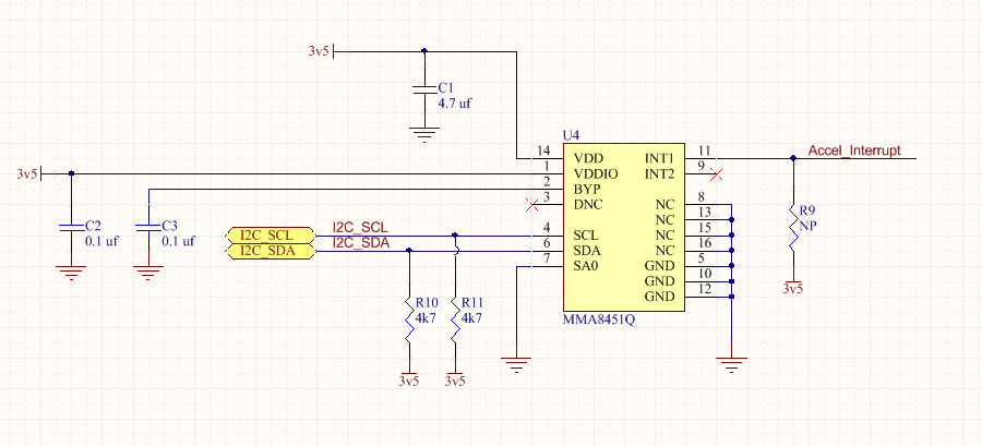
I have attached a pic of the schematic as to how it is wired. As required in the reference design, pin 3 ("DNC") is not connected and is floating. We did connect the "NC" pins to ground, though we removed the part from one board and cut those pads out (the "NC" pads, pins 8, 13, 15, 16) and re-installed the part and the behavior still persists.
We are ready to kick off production and we'd like to get a warm fuzzy feeling as to why this is happening and if it's safe to move ahead.
Any feedback much appreciated. Thanks!!
-K
Solved! Go to Solution.
- Mark as New
- Bookmark
- Subscribe
- Mute
- Subscribe to RSS Feed
- Permalink
- Report Inappropriate Content
Hi Peter,
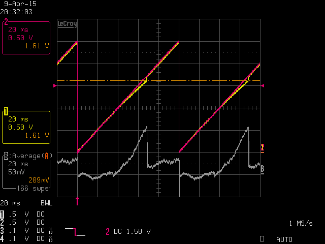
I've measured MMA845xQ current at low Vsupply but does not correlate with your findings. Basically I'm sending a sawtooth waveform on Vdd/VddIO with a LF sig gen (50ohm output impedance) and I'm measuring the voltage drop vs ideal waveform. I can seen a smooth current increase up to 2mA when Vsupply reaches about 1.7V, then current drops and stays at a much lower value, see attached o-scope plot as illustration.
You mentionned initially some interaction with Firmware (polling the FIFO solved the issue), I've also noticed on the schematic that INT1 is connected. Could there be any concern from there, GPIO conflict or whatever ?
This is the first time such current surge issue is reported so we need to figure it out.
- Mark as New
- Bookmark
- Subscribe
- Mute
- Subscribe to RSS Feed
- Permalink
- Report Inappropriate Content
I've witnessed what is likely the same effect in the MMA8453. When you lower the supply voltage to 1.0 < VDD <1.5V it begins to draw anomalously high current. I have also measured it peaking at around 1.8mA. I discovered this issue because the 15mA battery charger IC was unable to recharge dead batteries due to the MMA8453 drawing all of the charge current below 1.5v.
We solved the problem in a PCB revision by powering the MMA845X through a pin on the MCU, which shuts off power to the MMA845x when the voltage is < 2V.
Peter
- Mark as New
- Bookmark
- Subscribe
- Mute
- Subscribe to RSS Feed
- Permalink
- Report Inappropriate Content
Hi Peter,
I've measured MMA845xQ current at low Vsupply but does not correlate with your findings. Basically I'm sending a sawtooth waveform on Vdd/VddIO with a LF sig gen (50ohm output impedance) and I'm measuring the voltage drop vs ideal waveform. I can seen a smooth current increase up to 2mA when Vsupply reaches about 1.7V, then current drops and stays at a much lower value, see attached o-scope plot as illustration.
You mentionned initially some interaction with Firmware (polling the FIFO solved the issue), I've also noticed on the schematic that INT1 is connected. Could there be any concern from there, GPIO conflict or whatever ?
This is the first time such current surge issue is reported so we need to figure it out.
- Mark as New
- Bookmark
- Subscribe
- Mute
- Subscribe to RSS Feed
- Permalink
- Report Inappropriate Content
Hi Jaques,
Yes, I was wrong. I forgot the charger delivers only 5% of it's capacity at that voltage. I measured the same as you (peaking just under 2mA).
Sorry for the confusion - I have edited my original comment. It would be great if the datasheet mentioned this effect.
- Mark as New
- Bookmark
- Subscribe
- Mute
- Subscribe to RSS Feed
- Permalink
- Report Inappropriate Content
Hi Peter,
I'm glad we finally correlate on the part behavior.
Thanks for your investigation and feedback. I'll echo your suggestion about the datasheet to our tech writer.
For your information, we have completely suppressed this leakage current during Vsupply ramp-up on our more recent products.
Regards, Jacques.
- Mark as New
- Bookmark
- Subscribe
- Mute
- Subscribe to RSS Feed
- Permalink
- Report Inappropriate Content
Hi Jacques,
Is there a more recent version of the MMA8452Q that is recommended for new designs? I'm actually looking at revising our design for other reasons so if you can recommend an improved version or a similar but cheaper version that would be great. Thanks.
- Mark as New
- Bookmark
- Subscribe
- Mute
- Subscribe to RSS Feed
- Permalink
- Report Inappropriate Content
Hello Peter and Jacques,
Thank you for the responses. I apologize for the long delay in returning to the conversation as I have been traveling. I am quite embarrassed to admit there was indeed an I/O conflict on the interrupt line. Thank you so much for pointing that out. I was preoccupied with studying the I2C lines and did not consider the I/O line. Actually I did, but I assumed the host processor was pulling it low, verified the pin was set to input w/ pull-up and disregarded the INT line as a problem source. What I failed to consider was that there is another device sharing that interrupt line - a gyroscope. Turns out the default power-up configuration of that device is push-pull with the pin low. Once we set its registers to go back to open-drain mode, the current went away.
The discussion does raise a couple new questions though....
1) I too would like to know if there is a better part for new designs. We plan to order production boards on Monday and I'm hopeful there may be a pin-compatible part that we can drop in or add with a minimal board edit. Know that the reason we selected the MMA8452Q was because it is used by SparkFun for their accerometer break-out board. The product we are making is open source hardware (Ringo robot project) and wanted to use the same device as SparkFun has already published some code for it. But if there is an update, I'd love to check it out.
2) Would damage occur to the part if this line is constantly pulled low? I don't think so because we've had it pulled low for long periods of time and the part seems to continue to work fine once the conflicting part lets go of the INT line. From the DS, I wasn't able to determine what the internals of this pin look like. For now we will make sure we immediately set the conflicting device to open-drain in the startup script, but it would still be possible that a user (the bot is intended to be hacked by end users) to omit this and pull this line for long periods of time; not to mention that it will be briefly pulled anyway as the host micro starts up. Just want to make sure they're not going to damage anything. If there is a current limit for the pin, or if there is a resistor on the output, it would be great to know the value as I can add a small resistor between the conflicting devices to allow the line to still function the same but limit current to safe levels.
3) As a general rule, please communicate a request to chip designers: When a part starts up, in my opinion, all pins should *always* come up as inputs or in some high impedance mode so they don't pull on or drive attached circuits until configured to do so. Give the option, sure, but make it a mode that must be intentionally set. The offending part is a gyro from ST so the problem is not on Freescale, but still, as a designer that uses parts, I really wish chip designers would stick to this rule.
Thanks again so much for the help both of you and sorry for the false alarm.
-Kevin
- Mark as New
- Bookmark
- Subscribe
- Mute
- Subscribe to RSS Feed
- Permalink
- Report Inappropriate Content
Hi Kevin,
Thanks for sharing the root cause of the current surge and the background of your project. I saw the Ringo robot video and found it great.
1/ in term of alternate accelerometer choice, I would suggest MMA8652FC/MMA8653FC family, which has a smaller package (2x2mm footprint) and slightly lower price but similar performance and features. Register map is the same, unfortunately you will need to update the PCB layout.
2/ the 15-20mA current is not an issue for the INT output pin which has much higher capability, so no damage or reliability concern is expected. Obviously a small elevation of the package temperature will be observed due to this 60mW or so power dissipation. I guess main penalty for the user will be the battery life reduction.
3/ I understand the request and mostly subscribe to it, so will convey it to designers & product definers.
Regards, Jacques.