
- NXP Forums
- Product Forums
- General Purpose MicrocontrollersGeneral Purpose Microcontrollers
- i.MX Forumsi.MX Forums
- QorIQ Processing PlatformsQorIQ Processing Platforms
- Identification and SecurityIdentification and Security
- Power ManagementPower Management
- MCX Microcontrollers
- S32G
- S32K
- S32V
- MPC5xxx
- Other NXP Products
- Wireless Connectivity
- S12 / MagniV Microcontrollers
- Powertrain and Electrification Analog Drivers
- Sensors
- Vybrid Processors
- Digital Signal Controllers
- 8-bit Microcontrollers
- ColdFire/68K Microcontrollers and Processors
- PowerQUICC Processors
- OSBDM and TBDML
-
- Solution Forums
- Software Forums
- MCUXpresso Software and ToolsMCUXpresso Software and Tools
- CodeWarriorCodeWarrior
- MQX Software SolutionsMQX Software Solutions
- Model-Based Design Toolbox (MBDT)Model-Based Design Toolbox (MBDT)
- FreeMASTER
- eIQ Machine Learning Software
- Embedded Software and Tools Clinic
- S32 SDK
- S32 Design Studio
- GUI Guider
- Zephyr Project
- Voice Technology
- Application Software Packs
- Secure Provisioning SDK (SPSDK)
- Processor Expert Software
-
- Topics
- Mobile Robotics - Drones and RoversMobile Robotics - Drones and Rovers
- NXP Training ContentNXP Training Content
- University ProgramsUniversity Programs
- Rapid IoT
- NXP Designs
- SafeAssure-Community
- OSS Security & Maintenance
- Using Our Community
-
- Cloud Lab Forums
-
- RSS フィードを購読する
- トピックを新着としてマーク
- トピックを既読としてマーク
- このトピックを現在のユーザーにフロートします
- ブックマーク
- 購読
- ミュート
- 印刷用ページ
- 新着としてマーク
- ブックマーク
- 購読
- ミュート
- RSS フィードを購読する
- ハイライト
- 印刷
- 不適切なコンテンツを報告
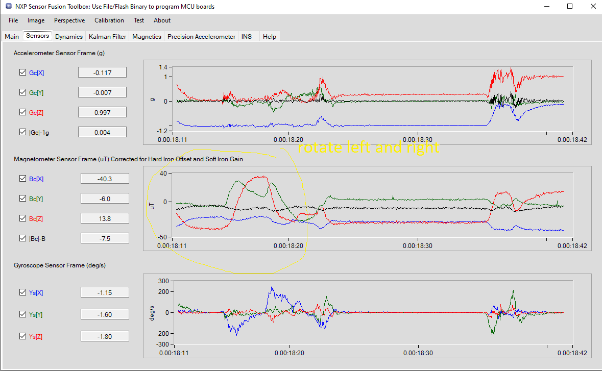
Hello, I am new to NXP. Currently, I am playing with NXP Sensor Fusion Toolbox with FRDM-STBC-AGM01. I have flashed the example Kinetis Binary using the Toolbox. The magnetometer is calibrated and saved to flash. Gyro Stabilized Compass is selected in algorithm tab.
But when I lift the the board to vertical (pitch to ~90)and rotate the board left and right, roll and compass increase/decrease together.
I know the Euler angle is converted from rotation matrix and is used for display only. Also, the rotation matrix is converted from quaternion in Kalman filter.
My questions:
1. Why gimbal behavior appeared? Isn't quaternion immune to gimbal Lock?
2. How to solve this gimbal lock problem?
Thank you.
解決済! 解決策の投稿を見る。
- 新着としてマーク
- ブックマーク
- 購読
- ミュート
- RSS フィードを購読する
- ハイライト
- 印刷
- 不適切なコンテンツを報告
Hello Leo,
please see a reply from the application engineer.
DESCRIPTION
Please refer to section 1.7 and 2.4 in AN5017( attached) which explains the gimbal lock and mathematics at gimbal lock position. From customer video, I can see him rotated PCB around the vertical axis at 90 degree pitch, the image would be following his rotation if the mag calibration worked good. The compass data may jump due to compass discontinuity at the gimbal lock position as board may change between face up and face down, but both roll and compass are not locked or oscillate randomly.
With Best Regards,
Jozef
- 新着としてマーク
- ブックマーク
- 購読
- ミュート
- RSS フィードを購読する
- ハイライト
- 印刷
- 不適切なコンテンツを報告
Hello Leo,
I have tested the FRDM-STBC-AGM01 in the Freedom Sensor Toolbox and you are right, the gimbal lock appeared, when the board is lifted 90 degrees in pitch direction.
Unfortunately the magnetometer in the FXOS8700CQ is not immune to the gimbal lock. The gimbal lock is due to the limitation of the Euler Angles calculation method. Please see this link: https://www.youtube.com/watch?v=q0jgqeS_ACM
With Best Regards,
Jozef
- 新着としてマーク
- ブックマーク
- 購読
- ミュート
- RSS フィードを購読する
- ハイライト
- 印刷
- 不適切なコンテンツを報告
Thanks for your reply.
Unfortunately the magnetometer in the FXOS8700CQ is not immune to the gimbal lock.
----------------------
I've been going through all the algorithm in NXP Sensor Fusion Toolbox. Gaming Handset algorithm that does not use magnetometer also shows gimbal lock symptom. Which means the problem is nothing about the magnetometer. It should be the algorithm itself.
The gimbal lock is due to the limitation of the Euler Angles calculation method.
------------------
I have checked NSFK_Prod_UG.pdf which stated that:
"Rotation matrices have the advantage of always being unique. Euler angles are subject to gimbal lock and should not be used for internal calculations (only input/output of results). "
In addition, I have a glance at NXP sensor fusion which use quaternion in most of the calculations. Isn't quaternion immune to gimbal Lock?
Is this a known issue for NXP sensor fusion? Finally, how to solve this gimbal lock problem?
- 新着としてマーク
- ブックマーク
- 購読
- ミュート
- RSS フィードを購読する
- ハイライト
- 印刷
- 不適切なコンテンツを報告
Hello Leo,
please see an answer from an application engineer I have contacted.
DESCRIPTION
I am not sure if my understanding is correct, does customer think on the 90 degree vertical pitch position, the roll and compass should not change, otherwise, he think this is gimbal lock? From my thoughts, the concept is just opposite. As customer mentioned, all 3 angles are calculated from rotation matrix, at 90 degree pitch, the sensor fusion still gives correct compass heading which aligned with the board direction.
With Best Regards,
Jozef
- 新着としてマーク
- ブックマーク
- 購読
- ミュート
- RSS フィードを購読する
- ハイライト
- 印刷
- 不適切なコンテンツを報告
I think I should explain this problem with a video for a better understanding of the issue.
Can you show this video to the engineer please?
-----------------
This video consists of two parts. First, pitch is stable when roll ~-90 degree.
Second, roll angle does not look right when pitch approach 90.
Is it gimbal lock?
- 新着としてマーク
- ブックマーク
- 購読
- ミュート
- RSS フィードを購読する
- ハイライト
- 印刷
- 不適切なコンテンツを報告
Hello Leo,
please see a reply from the application engineer.
DESCRIPTION
Please refer to section 1.7 and 2.4 in AN5017( attached) which explains the gimbal lock and mathematics at gimbal lock position. From customer video, I can see him rotated PCB around the vertical axis at 90 degree pitch, the image would be following his rotation if the mag calibration worked good. The compass data may jump due to compass discontinuity at the gimbal lock position as board may change between face up and face down, but both roll and compass are not locked or oscillate randomly.
With Best Regards,
Jozef
- 新着としてマーク
- ブックマーク
- 購読
- ミュート
- RSS フィードを購読する
- ハイライト
- 印刷
- 不適切なコンテンツを報告
I had a misunderstanding with gimbal lock and everything is clear now.
Thank you for clarifying my problem.
- 新着としてマーク
- ブックマーク
- 購読
- ミュート
- RSS フィードを購読する
- ハイライト
- 印刷
- 不適切なコンテンツを報告
Hi Mr Leo,
I am facing the same problem.. But i didn't understand the solution...
1st Problem is..
I rotated the board in Pitch direction... when pitch is beyond 75 Deg then Roll & Yaw increasing substantially (>45 Deg in each ) even though i didn't rotated board in Roll & yaw direction.. What is the root cause for this? How to Solve this problem?
2nd Problem is...
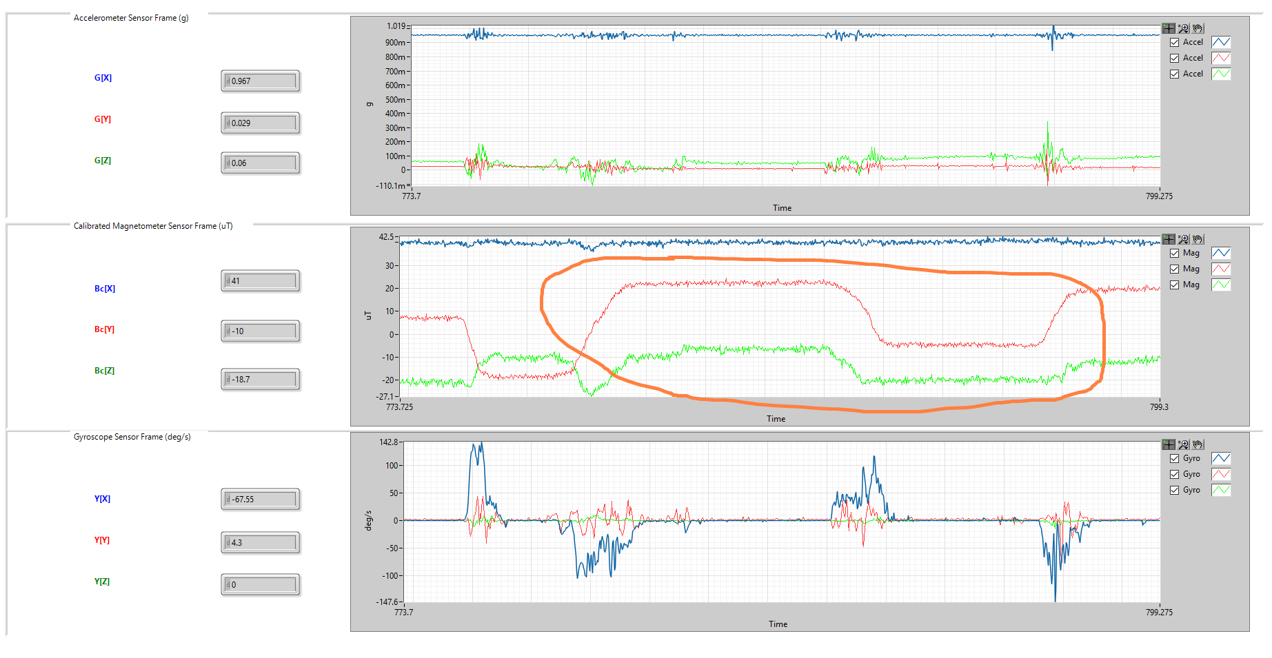
I have done magnetometer 12 parameter calibration and I got magnetic field strength B= 42 uT.
But when i rotated the board in different orientations at the same location B (computed as norm from magnetometer calibrated readings) is varying around 32uT to 52uT .. Since the location is not changed B shouldn't change but it is changing at the same location...
What is the reason for this?
Is this due to imperfect calibration due to noise in instant reading of magnetometer sensor FXOS8700CQ?
How to solve this problem?
Any help in this greatly appreciated.
Thank you,
Venkat.