
- Forums
- Product Forums
- General Purpose MicrocontrollersGeneral Purpose Microcontrollers
- i.MX Forumsi.MX Forums
- QorIQ Processing PlatformsQorIQ Processing Platforms
- Identification and SecurityIdentification and Security
- Power ManagementPower Management
- Wireless ConnectivityWireless Connectivity
- RFID / NFCRFID / NFC
- Advanced AnalogAdvanced Analog
- Neural Processing UnitsNeural Processing Units
- MCX Microcontrollers
- S32G
- S32K
- S32V
- MPC5xxx
- Other NXP Products
- S12 / MagniV Microcontrollers
- Powertrain and Electrification Analog Drivers
- Sensors
- Vybrid Processors
- Digital Signal Controllers
- 8-bit Microcontrollers
- ColdFire/68K Microcontrollers and Processors
- PowerQUICC Processors
- OSBDM and TBDML
- S32M
- S32Z/E
-
- Solution Forums
- Software Forums
- MCUXpresso Software and ToolsMCUXpresso Software and Tools
- CodeWarriorCodeWarrior
- MQX Software SolutionsMQX Software Solutions
- Model-Based Design Toolbox (MBDT)Model-Based Design Toolbox (MBDT)
- FreeMASTER
- eIQ Machine Learning Software
- Embedded Software and Tools Clinic
- S32 SDK
- S32 Design Studio
- GUI Guider
- Zephyr Project
- Voice Technology
- Application Software Packs
- Secure Provisioning SDK (SPSDK)
- Processor Expert Software
- Generative AI & LLMs
-
- Topics
- Mobile Robotics - Drones and RoversMobile Robotics - Drones and Rovers
- NXP Training ContentNXP Training Content
- University ProgramsUniversity Programs
- Rapid IoT
- NXP Designs
- SafeAssure-Community
- OSS Security & Maintenance
- Using Our Community
-
- Cloud Lab Forums
-
- Knowledge Bases
- ARM Microcontrollers
- i.MX Processors
- Identification and Security
- Model-Based Design Toolbox (MBDT)
- QorIQ Processing Platforms
- S32 Automotive Processing Platform
- Wireless Connectivity
- CodeWarrior
- MCUXpresso Suite of Software and Tools
- MQX Software Solutions
- RFID / NFC
- Advanced Analog
- Neural Processing Units
-
- NXP Tech Blogs
- Home
- :
- ソフトウェア・フォーラム
- :
- プロセッサ・エキスパート・ソフトウェア
- :
- Re: Re: I2C_LDD Component compiles without errors, silence on SDA, SCL pins
I2C_LDD Component compiles without errors, silence on SDA, SCL pins
- RSS フィードを購読する
- トピックを新着としてマーク
- トピックを既読としてマーク
- このトピックを現在のユーザーにフロートします
- ブックマーク
- 購読
- ミュート
- 印刷用ページ
- 新着としてマーク
- ブックマーク
- 購読
- ミュート
- RSS フィードを購読する
- ハイライト
- 印刷
- 不適切なコンテンツを報告
Hello,
I posted this question as open for the whole community (No activity on probes after successfully configuring and running I2C_LDD component) but it's been over two weeks so I am hoping this is a more appropriate place to post.
A brief summary; I am using Codewarrior 10.5 with Processor Expert. I've configured the I2C_LDD component and copied in sample code I found in Help On Component. I get no errors or warnings but when I go to run the code, the SDA and SCL pins are silent. I tried a fix I found on MCU on Eclipse (KL25Z and I2C: Missing Repeated Start Condition | MCU on Eclipse). I tried reducing the sample code as far down as just the I2C_Init function so I could just see the SCL pin running the clock. I contacted the manufacturer of the IC I am trying to communicate with and corrected my code as per their suggestion. All roads seem to point to the component configuration.
I've attached a copy of my initial attempt with the sample code. Later versions stripped out parts like the Term and Util and well as pieces of the code using I2C_LDD all the way down to just leaving the I2C_Init function. I put in the send string functions as a trouble shooting tool and I cannot see any besides the first one so whatever problem I am running into hits by the Init function call. Once I am communicating with the IC, I can reconnect with the manufacturer support but for now I could really use some advice on what's causing the silence.
Hope to hear from you,
Yusif Nurizade
Original Attachment has been moved to: I2C_Communication_Attempt_1_8b_2014.zip
解決済! 解決策の投稿を見る。
- 新着としてマーク
- ブックマーク
- 購読
- ミュート
- RSS フィードを購読する
- ハイライト
- 印刷
- 不適切なコンテンツを報告
All,
I've managed to resolve the issue I've been having and am posting the fix in case any one has a similar problem.
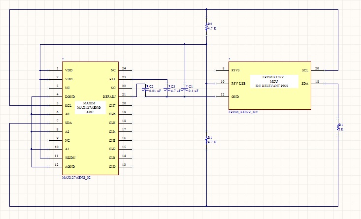
Originally, as seen in my wiring diagram, I wired the IC power and ground to the corresponding pins on the MCU. The digital logic analyzer showed the SDA and SCL pins as high so I did not think that the problem could be here. On a whim, however, I rewired on a powered prototyping board with a much higher current rating. As soon as I did this, I was able to see activity on both pins.
Thanks again for the help,
Yusif Nurizade
- 新着としてマーク
- ブックマーク
- 購読
- ミュート
- RSS フィードを購読する
- ハイライト
- 印刷
- 不適切なコンテンツを報告
All,
I've managed to resolve the issue I've been having and am posting the fix in case any one has a similar problem.
Originally, as seen in my wiring diagram, I wired the IC power and ground to the corresponding pins on the MCU. The digital logic analyzer showed the SDA and SCL pins as high so I did not think that the problem could be here. On a whim, however, I rewired on a powered prototyping board with a much higher current rating. As soon as I did this, I was able to see activity on both pins.
Thanks again for the help,
Yusif Nurizade
- 新着としてマーク
- ブックマーク
- 購読
- ミュート
- RSS フィードを購読する
- ハイライト
- 印刷
- 不適切なコンテンツを報告
Hi,
At first, please check that you have connected 4k7 pull-up resistor connected to I2C lines. The pins SDA, SCL should be "high" when no data are transferred from master.
Please check the error code that is returned by MasterSend/ReceiveBlock(). If the lines would not be in correct "IDLE" state, these methods would return ERR_BUSY.
To catch potential errors during communication, please enable the OnError event (in Events tab of the component inspector) and put some code there. To get detailed error information, use the GetError method.
Note: To enable these methods and events, you may need (If you already haven't do so) switch to Advance or Expert view mode (button at top-right in inspector view).
Please also note that the slave device has to be connected to the I2C pins, otherwise the communication always ends with an error, because the slave must send acknowledge after it receives the address etc..
Best regards
Petr Hradsky
Processor Expert Support Team
- 新着としてマーク
- ブックマーク
- 購読
- ミュート
- RSS フィードを購読する
- ハイライト
- 印刷
- 不適切なコンテンツを報告
Petr,
Thank you for your reply. I apologize for the late response but I wanted to make sure I tried everything before coming back to the forum.
With regard to your suggestions, the pull up resistors are in place (the pins show high as default), I've added the OnError event and am checking the error code in the Send/Receive blocks. When I run the code, I get back a single 0 which I believe corresponds to the Send block and ERR_OK. Even if the receive block is not going through, however, I am curious why I wouldn't see some activity on the I2C pins. I've tried both digital logic analyzer and oscilloscope probes thinking I may have set an insufficient thresh hold but the channels just stay high with no changes.
I've spoken to the slave device's manufacturer and they confirmed the code and wiring setup should be producing some communication on the line. After checking and double checking I must admit, I am a bit stumped and am hoping for some advice. To that end, I am attaching my code and a schematic of my wiring connections.
Hope to hear from you,
Yusif Nurizade