
- Forums
- Product Forums
- General Purpose MicrocontrollersGeneral Purpose Microcontrollers
- i.MX Forumsi.MX Forums
- QorIQ Processing PlatformsQorIQ Processing Platforms
- Identification and SecurityIdentification and Security
- Power ManagementPower Management
- MCX Microcontrollers
- S32G
- S32K
- S32V
- MPC5xxx
- Other NXP Products
- Wireless Connectivity
- S12 / MagniV Microcontrollers
- Powertrain and Electrification Analog Drivers
- Sensors
- Vybrid Processors
- Digital Signal Controllers
- 8-bit Microcontrollers
- ColdFire/68K Microcontrollers and Processors
- PowerQUICC Processors
- OSBDM and TBDML
-
- Solution Forums
- Software Forums
- MCUXpresso Software and ToolsMCUXpresso Software and Tools
- CodeWarriorCodeWarrior
- MQX Software SolutionsMQX Software Solutions
- Model-Based Design Toolbox (MBDT)Model-Based Design Toolbox (MBDT)
- FreeMASTER
- eIQ Machine Learning Software
- Embedded Software and Tools Clinic
- S32 SDK
- S32 Design Studio
- GUI Guider
- Zephyr Project
- Voice Technology
- Application Software Packs
- Secure Provisioning SDK (SPSDK)
- Processor Expert Software
- MCUXpresso Training Hub
-
- Topics
- Mobile Robotics - Drones and RoversMobile Robotics - Drones and Rovers
- NXP Training ContentNXP Training Content
- University ProgramsUniversity Programs
- Rapid IoT
- NXP Designs
- SafeAssure-Community
- OSS Security & Maintenance
- Using Our Community
-
- Cloud Lab Forums
-
- Knowledge Bases
- ARM Microcontrollers
- i.MX Processors
- Identification and Security
- Model-Based Design Toolbox (MBDT)
- QorIQ Processing Platforms
- S32 Automotive Processing Platform
- Wireless Connectivity
- CodeWarrior
- MCUXpresso Suite of Software and Tools
- MQX Software Solutions
-
- Home
- :
- 製品フォーラム
- :
- PowerQUICCプロセッサ
- :
- MPC8313--BDI print COP status is 0x05
MPC8313--BDI print COP status is 0x05
- RSS フィードを購読する
- トピックを新着としてマーク
- トピックを既読としてマーク
- このトピックを現在のユーザーにフロートします
- ブックマーク
- 購読
- ミュート
- 印刷用ページ
MPC8313--BDI print COP status is 0x05
- 新着としてマーク
- ブックマーク
- 購読
- ミュート
- RSS フィードを購読する
- ハイライト
- 印刷
- 不適切なコンテンツを報告
- 新着としてマーク
- ブックマーク
- 購読
- ミュート
- RSS フィードを購読する
- ハイライト
- 印刷
- 不適切なコンテンツを報告
On the target board, please ensue HRESET not tied to TRST, HRESET to the processor exclusive to COP/JTAG header. Problems arise when the core is reset and the debugger doesn't know about it, usually the debugger will report the processor cannot be put into STOP mode.
Please refer to page 5 in the attached PPT about JTAG interface design.
Thanks,
Yiping
- 新着としてマーク
- ブックマーク
- 購読
- ミュート
- RSS フィードを購読する
- ハイライト
- 印刷
- 不適切なコンテンツを報告
HRESET connect to the jtag(pin 13) directly,with a 1KΩ pull up resistor。
COP/JTAG‘s TRST(pin 4)use a or gate with the poreset to the CPU’TRST,and the COP/JTAG‘s TRST pull up with a 4.7K resistor。
It fits the page 5 of the PPT。
- 新着としてマーク
- ブックマーク
- 購読
- ミュート
- RSS フィードを購読する
- ハイライト
- 印刷
- 不適切なコンテンツを報告
Please make sure there is valid RCW on the target board.
- 新着としてマーク
- ブックマーク
- 購読
- ミュート
- RSS フィードを購読する
- ハイライト
- 印刷
- 不適切なコンテンツを報告
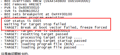
How can I do it? I have 5 board,four is in good condition,one occurs the problem as shown。Maybe I should replace the MPC8313?
- 新着としてマーク
- ブックマーク
- 購読
- ミュート
- RSS フィードを購読する
- ハイライト
- 印刷
- 不適切なコンテンツを報告
Hi Johnny
This essentially indicates that BDI issues a freeze command but the processor does not come to stopped state. It is probably because your board does not boot. You can disconnect the BDI and check with logic analyzer or oscilloscope to see if the processor tries to fetch the boot vector.
Regards
Sinan Akman
- 新着としてマーク
- ブックマーク
- 購読
- ミュート
- RSS フィードを購読する
- ハイライト
- 印刷
- 不適切なコンテンツを報告
thank you for your response。
The boot file can't program into the Flash now,I don't kown where can I fetch the boot vector without BDI。
I can get the ddrclk(MEMC_MCK/MEMC_MCK# ) when the BDI connected ,so it seems the PLL work up,the boot is running。But when the HRESET comes to high,the uart1 put nothing out。I have also measured the power supply、the power-on-reset sequence,they fit the specification of mpc8313。
so can you give some suggest ?
- 新着としてマーク
- ブックマーク
- 購読
- ミュート
- RSS フィードを購読する
- ハイライト
- 印刷
- 不適切なコンテンツを報告
Hi Johnny, please e-mail me your config file and I will take a look. Also I think you are doing RCW overwrite in your config via BDI. As Yipping suggests below, you need also make sure the RCW you are providing is valid and reflects your design. Send me your BDI config file directly as well information about your board as much as you can and I will take a look.
Regards
Sinan Akman
- 新着としてマーク
- ブックマーク
- 購読
- ミュート
- RSS フィードを購読する
- ハイライト
- 印刷
- 不適切なコンテンツを報告
Hi Sinan,
I'v send the config file.The board works with 33Mhz of sysclk,two piece of MT47H64M16NF DDR2 SDRAM.More infomations as below:
--
Clock configuration:
Coherent System Bus: 166 MHz
Core: 333 MHz
Local Bus Controller: 166 MHz
Local Bus: 41 MHz
DDR: 333 MHz
SEC: 55 MHz
I2C1: 166 MHz
I2C2: 166 MHz
TSEC1: 166 MHz
TSEC2: 166 MHz
USB MPH: 0 MHz
USB DR: 55 MHz
CPU: MPC8313E, Rev: 21 at 333.333 MHz
INFO: Initializing IOMEM for regset 0
INFO: reset phy for M88E1322 card
DRAM: 256 MB
NAND: 256 MB
Using default environment
--