
- NXP Forums
- Product Forums
- General Purpose MicrocontrollersGeneral Purpose Microcontrollers
- i.MX Forumsi.MX Forums
- QorIQ Processing PlatformsQorIQ Processing Platforms
- Identification and SecurityIdentification and Security
- Power ManagementPower Management
- MCX Microcontrollers
- S32G
- S32K
- S32V
- MPC5xxx
- Other NXP Products
- Wireless Connectivity
- S12 / MagniV Microcontrollers
- Powertrain and Electrification Analog Drivers
- Sensors
- Vybrid Processors
- Digital Signal Controllers
- 8-bit Microcontrollers
- ColdFire/68K Microcontrollers and Processors
- PowerQUICC Processors
- OSBDM and TBDML
-
- Solution Forums
- Software Forums
- MCUXpresso Software and ToolsMCUXpresso Software and Tools
- CodeWarriorCodeWarrior
- MQX Software SolutionsMQX Software Solutions
- Model-Based Design Toolbox (MBDT)Model-Based Design Toolbox (MBDT)
- FreeMASTER
- eIQ Machine Learning Software
- Embedded Software and Tools Clinic
- S32 SDK
- S32 Design Studio
- GUI Guider
- Zephyr Project
- Voice Technology
- Application Software Packs
- Secure Provisioning SDK (SPSDK)
- Processor Expert Software
-
- Topics
- Mobile Robotics - Drones and RoversMobile Robotics - Drones and Rovers
- NXP Training ContentNXP Training Content
- University ProgramsUniversity Programs
- Rapid IoT
- NXP Designs
- SafeAssure-Community
- OSS Security & Maintenance
- Using Our Community
-
- Cloud Lab Forums
-
- Home
- :
- Product Forums
- :
- Other NXP Products
- :
- Re: Fast reset of an HCS12 microcontroller
Fast reset of an HCS12 microcontroller
- Subscribe to RSS Feed
- Mark Topic as New
- Mark Topic as Read
- Float this Topic for Current User
- Bookmark
- Subscribe
- Mute
- Printer Friendly Page
Fast reset of an HCS12 microcontroller
- Mark as New
- Bookmark
- Subscribe
- Mute
- Subscribe to RSS Feed
- Permalink
- Report Inappropriate Content
I am trying to reset my MC9S12DT128 microcontroller in a short period of time (<20mS). Currently, I am using the watchdog timer to do that which takes 25-27mS which is too long for me. I want to achieve less than 10mS. The reset takes less than 1mS using the external Reset pin, but I cannot change the hardware and connect a GPIO to the external Reset pin.
I am looking for a pure firmware solution. Does anyone have an experience doing this? How can I improve the reset time using the watchdog or how can I have another way of resetting with firmware?
I am also looking into loss of clock resetting, but I don't think it is possible to use this method when the clock is fine. Any help is appreciated.
- Mark as New
- Bookmark
- Subscribe
- Mute
- Subscribe to RSS Feed
- Permalink
- Report Inappropriate Content
@lama Thank you for your help. I could resolve this issue by modifying the watchdog reset interrupt. Now it's as fast as the power on reset. But the problem now is that I need to update the bootloader in the next firmware which is not possible to do with over-the-air updates and we need to send someone to each site or ship the units here which increases the cost significantly. I am now thinking of other solutions like changing the default value of a GPIO upon reset. I realize that the default value of a GPIO is 1 but I want t see if it is possible to change it somehow. I appreciate it if you could think of any other solution that doesn't need a bootloader upgrade. Thanks,
- Mark as New
- Bookmark
- Subscribe
- Mute
- Subscribe to RSS Feed
- Permalink
- Report Inappropriate Content
Hi,
I have been thinking about your issue and discussing it with colleagues.
If your current bootloader uses pin to decide whether to start app or bootloader then we see no solution. The reset status of the pin is input and its default value depends on fact whether internal pull device is connected after reset and what is connected to the pin externally. If the pull device is not connected by default and there is nothing connected to the pin then the read value is random – pin is floating.
Best regards,
Ladislav
- Mark as New
- Bookmark
- Subscribe
- Mute
- Subscribe to RSS Feed
- Permalink
- Report Inappropriate Content
- Mark as New
- Bookmark
- Subscribe
- Mute
- Subscribe to RSS Feed
- Permalink
- Report Inappropriate Content
- Mark as New
- Bookmark
- Subscribe
- Mute
- Subscribe to RSS Feed
- Permalink
- Report Inappropriate Content
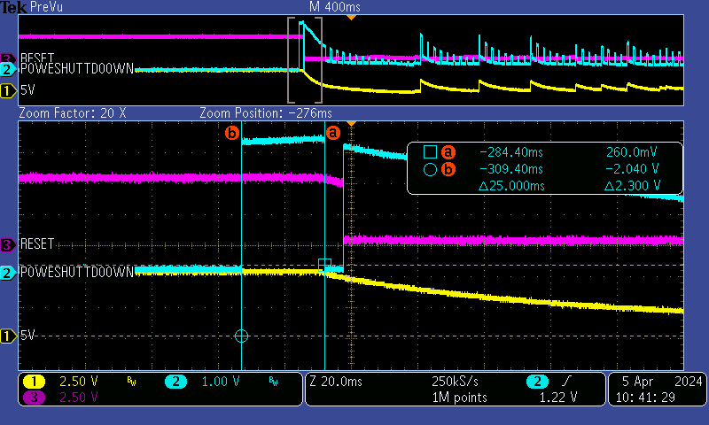
@lama Thank you for your response. I have attached the scope capture of the Reset pin of the micro along with a GPIO to show how long it takes for the micro to come back. My test GPIO, named POWER_SHUTDOWN, is cleared at the beginning of the code as soon as the micro is alive and running the code. But this pin is set by default after a reset. Therefore, the pulse width of this pin shows the time it takes for the micro to come back from a reset to a state that runs the code.
As you see, the reset pin goes low when the reset is initiated for a brief period of time, ~8uS. At the same time that the micro is being reset, i.e. the Reset pin is low, my test GPIO, POWER_SHUTDOWN, is being set by default. As soon as the micro comes back, the code clears this GPIO. Therefore, the pulse width of the POWER_SHUTDOWN GPIO shows the time it takes for the micro to reset and start running the initialization process from line 1. As you see this time is 25mS. Therefore, the code can successfully reset the micro but the micro won't be able to come back and start running its code in a timely manner. So my question is based on your comment, this issue can come either from watchdog reset vector or stack. What do you think?
- Mark as New
- Bookmark
- Subscribe
- Mute
- Subscribe to RSS Feed
- Permalink
- Report Inappropriate Content
There is no reason to be the reset so long.
If you write to the ARMCOP register different value from sequence 0x55,0xAA then the CRG immediately generates a reset.
In order to understand reset timing read S12CRGV4 block user guide. (5.2 Description of Reset Operation)
The system then count given amount of the BUSCLK to recognize source of the reset.
Possible issues when COP is not recognized and/or incorrectly processed:
If there is big capacitor on the reset pin then COP is not recognized and the MCU continues with POR. IF COP is correctly recognized then you have to have correctly written service routine for COP reset.
1) If reset pin contains high capacitance the watch dog reset is not recognized. (Remove capacitance from the pin or use capacitor as low as possible; less than 10nF)
Also BDM connected to the reset pin can cause the COP is not recognized.
2) Watchdog reset vector is not served – programmer’s mistake
3) Programmer does some operations which use stack; Stack is not initialized after WD reset => code is wandering
…attached example (DP256B - COP (WATCHDOG) - CW31.ZIP) for family device but really old CodeWarrior v.3.1 but the C cod is the same for newer versions.
Best regards,
Ladislav
- Mark as New
- Bookmark
- Subscribe
- Mute
- Subscribe to RSS Feed
- Permalink
- Report Inappropriate Content
Hi,
Something wrong must be in your code or design at the reset pin (for example SBC chip connected)
please look at the code and measurement…. The code is made for DT256.
I suggest to toggle pin immediately in the COP routine to see how fast the wake up is.
! The measurement must be done with BDM interface disconnected !
- Blue = reset pin
- Yellow = PTA.0, … after PTA.0 is cleared COP is generated by writing CPMUARMCOP=0x00;
- Reset takes 8.5us then the MCU jump into the COP reset routine where PTA.0 is set
- The low level period of the yellow takes 15.5us. (Time between COP generated and wake up visualization at the pin)
BUSCLK is set for 8MHz.

//******************************************************************************
// File Name : Main.c
// Description : COP example
// $Version : 0.1.0.0$
// $Date : 2024-04-11$
//******************************************************************************
// The SW demonstrates COP watchdog using and MCU start after COP reset
// It uses COP interrupt vector which is called after COP reset and inside the
// COP interrupt it calls first program function _Startup() => Starts program from
// the beginning.
// The reset could be done in two ways on the base of enabled line in the Local
// definitions part of the code:
// a) COP is enabled and wait till its period is over
// b) COP is enabled and the MCU is immediately reset by writing a value
// to ARMCOP other than the COP reset value.
//******************************************************************************
#include <hidef.h> /* common defines and macros */
#include "derivative.h" /* derivative-specific definitions */
//******************************************************************************
// CONDITIONAL COMPILATION SETUP
//******************************************************************************
#define HWA_ISSUE
//#undef HWA_ISSUE
//******************************************************************************
// Local definitions
//******************************************************************************
//******************************************************************************
// Local types definitions
//******************************************************************************
#define UBYTE unsigned char
#define SBYTE char
#define UWORD unsigned int
//******************************************************************************
#pragma DATA_SEG DEFAULT
//******************************************************************************
// Global variables
//******************************************************************************
static volatile UWORD j,k; // software delay constant
//******************************************************************************
#pragma CODE_SEG DEFAULT
//******************************************************************************
// Local functions definitions
//******************************************************************************
void main(void);
void _Startup(void);
//******************************************************************************
// WATCH DOG ISR
//******************************************************************************
#pragma CODE_SEG NON_BANKED
interrupt 2 void WatchDogIsr(void)
{
// WARNING: used wariable "j" has to be a global or static
// Note 1: port has to be set as an output again, since MCU was in reset
// Note 2: !!! stack pointer is not set after reset => any using stack before
// initialization can cause program crash
// (made inside the function _Startup)
// Note 3: Be aware that all registers are set to the RESET status. The RAM
// remains unchanged.
//--- Visualize COP reset on the port B diodes ---
// Note that you have to set the port as output, since MCU was in reset
PORTA = 0xFF; // set LEDs
DDRA = 0xff; // PTB as output
// for (j = 0;j < 0x20;j++) // wait to be able to recognize reset on the diodes
// { for(k=0;k<0xFFFF;k++) asm (nop);
// PORTA=~PORTA;
//
}
//--------------------------------------------
// run the program from the beginning
// startup code of the CodeWarrior S12 environment: void _Startup(void)
// located in the file Start12.c -> project tree directory: Startup Code
// you can us either this code (better solution)
asm JMP _Startup; // this code jumps to the _Startup
// or this code
// _Startup(); // this code leaves one address on the stack which
// has to be set because
}
//******************************************************************************
// MAIN
//******************************************************************************
#pragma CODE_SEG DEFAULT
void main(void)
{
//---------------------------------------
//--- Visualize start of main routine ---
PORTA = 0xFF;
DDRA = 0xff; // PORTB as output
PEAR_NECLK = 0; // BUSCLK at PE4
//--------------------------------------
for(;;)
{
for(j=0;j<255;j++)
{
for (j = 0;j < 0x01;j++) {for(k=0;k<0xFFFF;k++) { asm nop;}}
if(j=16)
{
COPCTL = 0x41; // enable COP
PORTA = 0x00;
ARMCOP = 0x00; // reset MCU immediately by means of COP
}
}
}
//--------------------------------------
while(1); // wait for COP reset
}
//--------------------------------------------------------------------------------------------------------------
Best regards,
Ladislav