
- Forums
- Product Forums
- General Purpose MicrocontrollersGeneral Purpose Microcontrollers
- i.MX Forumsi.MX Forums
- QorIQ Processing PlatformsQorIQ Processing Platforms
- Identification and SecurityIdentification and Security
- Power ManagementPower Management
- MCX Microcontrollers
- S32G
- S32K
- S32V
- MPC5xxx
- Other NXP Products
- Wireless Connectivity
- S12 / MagniV Microcontrollers
- Powertrain and Electrification Analog Drivers
- Sensors
- Vybrid Processors
- Digital Signal Controllers
- 8-bit Microcontrollers
- ColdFire/68K Microcontrollers and Processors
- PowerQUICC Processors
- OSBDM and TBDML
-
- Solution Forums
- Software Forums
- MCUXpresso Software and ToolsMCUXpresso Software and Tools
- CodeWarriorCodeWarrior
- MQX Software SolutionsMQX Software Solutions
- Model-Based Design Toolbox (MBDT)Model-Based Design Toolbox (MBDT)
- FreeMASTER
- eIQ Machine Learning Software
- Embedded Software and Tools Clinic
- S32 SDK
- S32 Design Studio
- GUI Guider
- Zephyr Project
- Voice Technology
- Application Software Packs
- Secure Provisioning SDK (SPSDK)
- Processor Expert Software
- MCUXpresso Training Hub
-
- Topics
- Mobile Robotics - Drones and RoversMobile Robotics - Drones and Rovers
- NXP Training ContentNXP Training Content
- University ProgramsUniversity Programs
- Rapid IoT
- NXP Designs
- SafeAssure-Community
- OSS Security & Maintenance
- Using Our Community
-
- Cloud Lab Forums
-
- Knowledge Bases
- Home
- :
- 汎用マイクロコントローラ
- :
- LPCマイクロコントローラ
- :
- UART sample code on LPC5526JBD64E MCU
UART sample code on LPC5526JBD64E MCU
- RSS フィードを購読する
- トピックを新着としてマーク
- トピックを既読としてマーク
- このトピックを現在のユーザーにフロートします
- ブックマーク
- 購読
- ミュート
- 印刷用ページ
- 新着としてマーク
- ブックマーク
- 購読
- ミュート
- RSS フィードを購読する
- ハイライト
- 印刷
- 不適切なコンテンツを報告
Hi,
I have two boards, one is LPC55S28-EVK, the other has LPC5526JBD64E on it.
I downloaded SDK_2_7_0_LPCXpresso55S28, then imported the hello world demo application.
I try to develop more functions based on the demo application.
I found the output debug message from the UART port(PIO0_29/PIO0_30) on LPC55S28-EVK, however, no message on my board with LPC5526JBD64E MCU...
I was wondering could you tell me how I should modify the demo application to make it run successfully on LPC5526JBD64E?
It is my way to download the image into MCU on-chip flash.
- Enter ISP mode.
- Download the image by tool Flash Magic.
- Change to passive mode.
- Power on the board.
BR,
carter
解決済! 解決策の投稿を見る。
- 新着としてマーク
- ブックマーク
- 購読
- ミュート
- RSS フィードを購読する
- ハイライト
- 印刷
- 不適切なコンテンツを報告
Hi Carter,
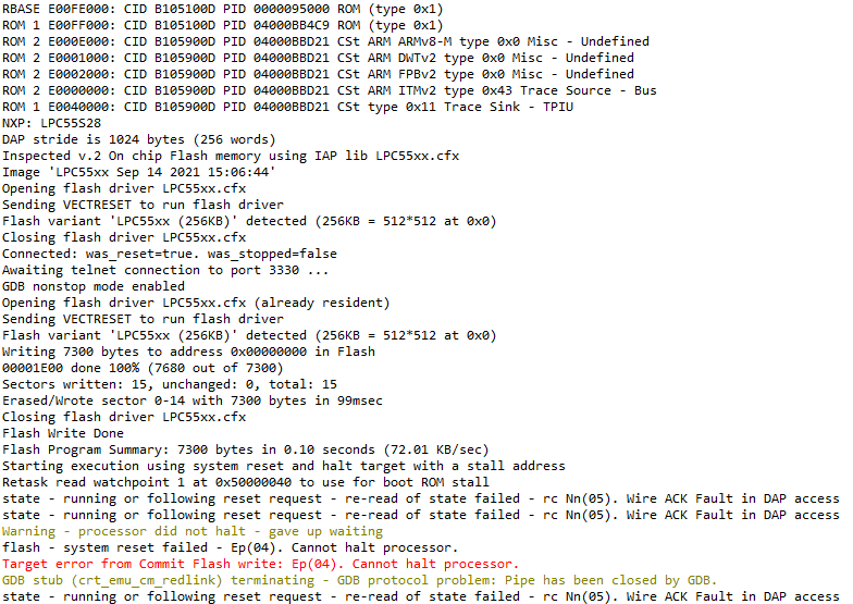
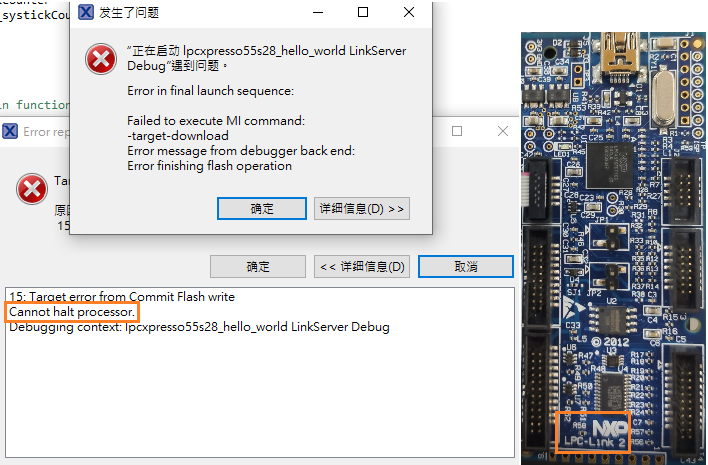
Are you using the LPC-Link 2 to debug the LPC5526 or the LPC55S28-EVK? Either way, I believe you should check out these posts in hopes of regaining debug access to your MCU:
https://community.nxp.com/t5/LPCXpresso-IDE-FAQs/Regaining-debug-access-to-target-MCU/m-p/473923
https://community.nxp.com/t5/LPCXpresso-IDE-FAQs/ISP-Reset-over-debug/m-p/470945
With respect to the demo application, I would recommend creating a new project for the LPC5526 with the necessary drivers and copying the source files only, instead of importing the whole project. This is because the project often comes with chip or board specific configurations and can cause problems.
I hope this helps,
Edwin.
- 新着としてマーク
- ブックマーク
- 購読
- ミュート
- RSS フィードを購読する
- ハイライト
- 印刷
- 不適切なコンテンツを報告
The problem might be due to the differences in pin assignments. I believe the LPC55S28-EVK comes with a LPC55S28JBD100 (please confirm this on your board) which is a 100 terminal package. The LPC5526JBD64, however, is a 64 pin package. Please make sure the pin assignments match the UART port of the LPC5526 as well, and that you are reading the UART port accordingly for the correct pins of this part number.
Best regards,
Edwin.
- 新着としてマーク
- ブックマーク
- 購読
- ミュート
- RSS フィードを購読する
- ハイライト
- 印刷
- 不適切なコンテンツを報告
- 新着としてマーク
- ブックマーク
- 購読
- ミュート
- RSS フィードを購読する
- ハイライト
- 印刷
- 不適切なコンテンツを報告
Hi Carter,
Are you using the LPC-Link 2 to debug the LPC5526 or the LPC55S28-EVK? Either way, I believe you should check out these posts in hopes of regaining debug access to your MCU:
https://community.nxp.com/t5/LPCXpresso-IDE-FAQs/Regaining-debug-access-to-target-MCU/m-p/473923
https://community.nxp.com/t5/LPCXpresso-IDE-FAQs/ISP-Reset-over-debug/m-p/470945
With respect to the demo application, I would recommend creating a new project for the LPC5526 with the necessary drivers and copying the source files only, instead of importing the whole project. This is because the project often comes with chip or board specific configurations and can cause problems.
I hope this helps,
Edwin.
- 新着としてマーク
- ブックマーク
- 購読
- ミュート
- RSS フィードを購読する
- ハイライト
- 印刷
- 不適切なコンテンツを報告
Hi Edwin,
Thanks for your information.
It is workable now.
BR,
carter