
- Forums
- Product Forums
- General Purpose MicrocontrollersGeneral Purpose Microcontrollers
- i.MX Forumsi.MX Forums
- QorIQ Processing PlatformsQorIQ Processing Platforms
- Identification and SecurityIdentification and Security
- Power ManagementPower Management
- Wireless ConnectivityWireless Connectivity
- RFID / NFCRFID / NFC
- Advanced AnalogAdvanced Analog
- Neural Processing UnitsNeural Processing Units
- MCX Microcontrollers
- S32G
- S32K
- S32V
- MPC5xxx
- Other NXP Products
- S12 / MagniV Microcontrollers
- Powertrain and Electrification Analog Drivers
- Sensors
- Vybrid Processors
- Digital Signal Controllers
- 8-bit Microcontrollers
- ColdFire/68K Microcontrollers and Processors
- PowerQUICC Processors
- OSBDM and TBDML
- S32M
- S32Z/E
-
- Solution Forums
- Software Forums
- MCUXpresso Software and ToolsMCUXpresso Software and Tools
- CodeWarriorCodeWarrior
- MQX Software SolutionsMQX Software Solutions
- Model-Based Design Toolbox (MBDT)Model-Based Design Toolbox (MBDT)
- FreeMASTER
- eIQ Machine Learning Software
- Embedded Software and Tools Clinic
- S32 SDK
- S32 Design Studio
- GUI Guider
- Zephyr Project
- Voice Technology
- Application Software Packs
- Secure Provisioning SDK (SPSDK)
- Processor Expert Software
- Generative AI & LLMs
-
- Topics
- Mobile Robotics - Drones and RoversMobile Robotics - Drones and Rovers
- NXP Training ContentNXP Training Content
- University ProgramsUniversity Programs
- Rapid IoT
- NXP Designs
- SafeAssure-Community
- OSS Security & Maintenance
- Using Our Community
-
- Cloud Lab Forums
-
- Knowledge Bases
- ARM Microcontrollers
- i.MX Processors
- Identification and Security
- Model-Based Design Toolbox (MBDT)
- QorIQ Processing Platforms
- S32 Automotive Processing Platform
- Wireless Connectivity
- CodeWarrior
- MCUXpresso Suite of Software and Tools
- MQX Software Solutions
- RFID / NFC
- Advanced Analog
- Neural Processing Units
-
- NXP Tech Blogs
- Home
- :
- General Purpose Microcontrollers
- :
- LPC Microcontrollers
- :
- Re: LPC1549 USB IAP
LPC1549 USB IAP
- Subscribe to RSS Feed
- Mark Topic as New
- Mark Topic as Read
- Float this Topic for Current User
- Bookmark
- Subscribe
- Mute
- Printer Friendly Page
LPC1549 USB IAP
- Mark as New
- Bookmark
- Subscribe
- Mute
- Subscribe to RSS Feed
- Permalink
- Report Inappropriate Content
Hello all,
I have just made a new PCB with an LPC1549 - 48 on it.
Absolute minimum parts,
USB connection, P2-12, P2-13
Pull-up’s for:
Reset,
ISP-0, P0-4
ISP-1 P0-16
I2C, P0-23, P0-22
CAN-TXD P0-13
CAN-RXD P0-18
Serial P0-15, P0-14
12 Mhz Crystal
And 2 LED’s
My problem is it does NOT show up as a USB Device, for programming,
It is not even coming up as a BAD Device !!
ISP-0 Low & ISP-1 Hi, and a negative going pulse on reset,
with reset low, my board takes about 4mA
When Hi around 9mA
I have made several other PCB designs, with USB enabled chips,
And they have worked OK.
Is there something I am missing, I have searched the data sheet for … you must …
or other Gothcers !!!
I can not see anything in the Espresso board that is relay different,
Other than I am using a 48 pin part not 64 pin part.
I am confident most of the board works, because I can enter serial ISP, and send “?”
and get
“Synchronized” back !!
But of course, using my work PC , I cannot install Flash Magic, or Bin2Hex
Only ‘APPROVED’ software is permitted
Any one has any suggestions,
I would appreciate it,
Cheers
Ceri
- Mark as New
- Bookmark
- Subscribe
- Mute
- Subscribe to RSS Feed
- Permalink
- Report Inappropriate Content
Well that's embarrassing ....
Changed the caps for the 12MHz Crystal to 12pf,
and it worked !!
I am sure there were 15 of 18 pf
- Mark as New
- Bookmark
- Subscribe
- Mute
- Subscribe to RSS Feed
- Permalink
- Report Inappropriate Content
Hello ceri,
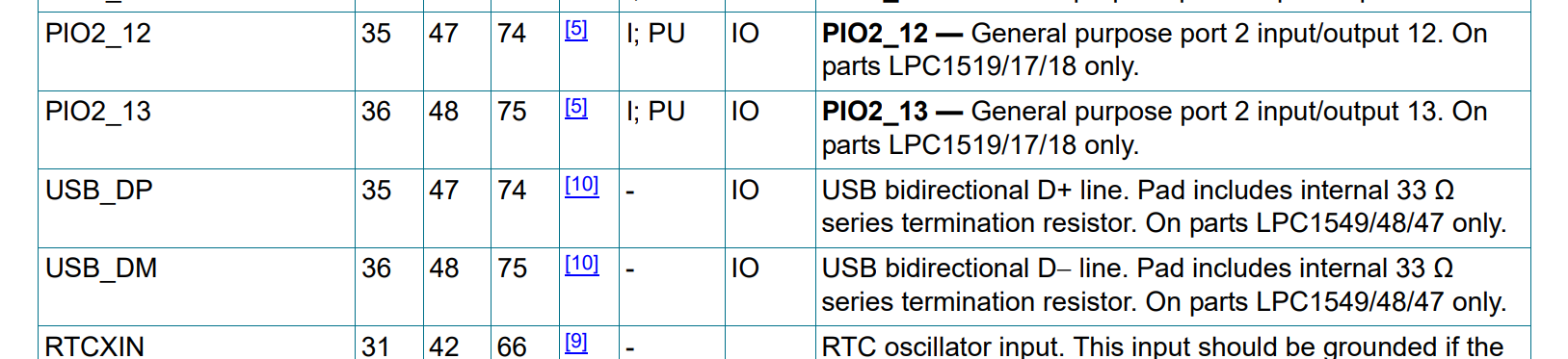
"USB connection, P2-12, P2-13"
LPC1549 doesn't have the two pins:

Regards,
Alice
- Mark as New
- Bookmark
- Subscribe
- Mute
- Subscribe to RSS Feed
- Permalink
- Report Inappropriate Content
- Mark as New
- Bookmark
- Subscribe
- Mute
- Subscribe to RSS Feed
- Permalink
- Report Inappropriate Content
Pin 35/36 is indeed USB pins (only) on the QFP48, I use this:

- Mark as New
- Bookmark
- Subscribe
- Mute
- Subscribe to RSS Feed
- Permalink
- Report Inappropriate Content
This is my version:

And the copper:

with CAN circuitry as well,
There is a 100R resistor in C16 slot, pulling RTX-IN low (as in data sheet, if not used)
I am still not able to get USB IAP to work.
I notice though two things, on your schematic:
Boot 0 and Boot 1 connected, which I believe means you can only go into serial boot (I need USB Programming)
and those are not the CAN pins for 48 pin device ?
- Mark as New
- Bookmark
- Subscribe
- Mute
- Subscribe to RSS Feed
- Permalink
- Report Inappropriate Content
You need of course to set the correct ISP mode.
You can run CAN on any pins
I use:
// CAN signal muxing LQFP48
Chip_SWM_MovablePortPinAssign(SWM_CAN_TD1_O , 0, 27); // P0.27 CAN TxD
Chip_SWM_MovablePortPinAssign(SWM_CAN_RD1_I, 0, 28); // P0.28 CAN RxD