- NXP Forums
- Product Forums
- General Purpose MicrocontrollersGeneral Purpose Microcontrollers
- i.MX Forumsi.MX Forums
- QorIQ Processing PlatformsQorIQ Processing Platforms
- Identification and SecurityIdentification and Security
- Power ManagementPower Management
- MCX Microcontrollers
- S32G
- S32K
- S32V
- MPC5xxx
- Other NXP Products
- Wireless Connectivity
- S12 / MagniV Microcontrollers
- Powertrain and Electrification Analog Drivers
- Sensors
- Vybrid Processors
- Digital Signal Controllers
- 8-bit Microcontrollers
- ColdFire/68K Microcontrollers and Processors
- PowerQUICC Processors
- OSBDM and TBDML
-
- Solution Forums
- Software Forums
- MCUXpresso Software and ToolsMCUXpresso Software and Tools
- CodeWarriorCodeWarrior
- MQX Software SolutionsMQX Software Solutions
- Model-Based Design Toolbox (MBDT)Model-Based Design Toolbox (MBDT)
- FreeMASTER
- eIQ Machine Learning Software
- Embedded Software and Tools Clinic
- S32 SDK
- S32 Design Studio
- Vigiles
- GUI Guider
- Zephyr Project
- Voice Technology
- Application Software Packs
- Secure Provisioning SDK (SPSDK)
- Processor Expert Software
-
- Topics
- Mobile Robotics - Drones and RoversMobile Robotics - Drones and Rovers
- NXP Training ContentNXP Training Content
- University ProgramsUniversity Programs
- Rapid IoT
- NXP Designs
- SafeAssure-Community
- OSS Security & Maintenance
- Using Our Community
-
- Cloud Lab Forums
-
- Home
- :
- MCUXpressoソフトウェアとツール
- :
- Kinetisソフトウェア開発キット・ナレッジベース
- :
- DAC Sinus Demo (using PEx + KSDK 1.2 + KDS 3.0)
DAC Sinus Demo (using PEx + KSDK 1.2 + KDS 3.0)
- RSS フィードを購読する
- 新着としてマーク
- 既読としてマーク
- ブックマーク
- 購読
- 印刷用ページ
- 不適切なコンテンツを報告
DAC Sinus Demo (using PEx + KSDK 1.2 + KDS 3.0)
DAC Sinus Demo (using PEx + KSDK 1.2 + KDS 3.0)
Created DAC Sinus example is PIT triggered with own buffer and is for FRDM-K64F.
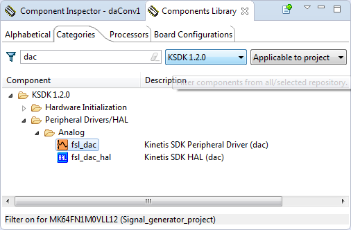
- adding analog component fsl_dac peripheral driver to project
- setting Voltage reference - Reference 2 for dac component (daConv1:fsl_dac)
- adding timer component fsl_pit peripheral driver to project
- setting period on 1 ms and enabling interrupts for timer component (pitTimer1:fsl_pit)
- setting buffer for sinusoidal in Sources -> Events.c
#define DAC_TEST_BUFF_SIZE (120U) uint16_t dac_buffer[DAC_TEST_BUFF_SIZE] = { 0x7ff, 0x86a, 0x8d5, 0x93f, 0x9a9, 0xa11, 0xa78, 0xadd, 0xb40, 0xba1, 0xbff, 0xc5a, 0xcb2, 0xd08, 0xd59, 0xda7, 0xdf1, 0xe36, 0xe77, 0xeb4, 0xeec, 0xf1f, 0xf4d, 0xf77, 0xf9a, 0xfb9, 0xfd2, 0xfe5, 0xff3, 0xffc, 0xfff, 0xffc, 0xff3, 0xfe5, 0xfd2, 0xfb9, 0xf9a, 0xf77, 0xf4d, 0xf1f, 0xeec, 0xeb4, 0xe77, 0xe36, 0xdf1, 0xda7, 0xd59, 0xd08, 0xcb2, 0xc5a, 0xbff, 0xba1, 0xb40, 0xadd, 0xa78, 0xa11, 0x9a9, 0x93f, 0x8d5, 0x86a, 0x7ff, 0x794, 0x729, 0x6bf, 0x655, 0x5ed, 0x586, 0x521, 0x4be, 0x45d, 0x3ff, 0x3a4, 0x34c, 0x2f6, 0x2a5, 0x257, 0x20d, 0x1c8, 0x187, 0x14a, 0x112, 0xdf, 0xb1, 0x87, 0x64, 0x45, 0x2c, 0x19, 0xb, 0x2, 0x0, 0x2, 0xb, 0x19, 0x2c, 0x45, 0x64, 0x87, 0xb1, 0xdf, 0x112, 0x14a, 0x187, 0x1c8, 0x20d, 0x257, 0x2a5, 0x2f6, 0x34c, 0x3a4, 0x3ff, 0x45d, 0x4be, 0x521, 0x586, 0x5ed, 0x655, 0x6bf, 0x729, 0x794 }; uint16_t index = 0; void pitTimer1_IRQHandler(void) { /* Clear interrupt flag.*/ PIT_HAL_ClearIntFlag(g_pitBase[FSL_PITTIMER1], FSL_PITTIMER1_CHANNEL); /* Write your code here ... */ DAC_DRV_Output(FSL_DACONV1,dac_buffer[index++]); if(index==DAC_TEST_BUFF_SIZE) index = 0; }
- FRDM-K64F with SALEAE
- sinusoidal output
Enjoy!
- 既読としてマーク
- 新着としてマーク
- ブックマーク
- ハイライト
- 印刷
- 不適切なコンテンツを報告
Hi Iva,
The example was very very usefull :smileyhappy:.
Just a question:
How do you make your buffer to generate a signal? I use EXCEL to do so, but, is there any other way to do it?
Thanks,
Jordan c:
- 既読としてマーク
- 新着としてマーク
- ブックマーク
- ハイライト
- 印刷
- 不適切なコンテンツを報告
Hello Jordan,
thank you for the question, I forget mentioned it.
For getting these values you can count it :-) or put them to Sine Generator with values for max amplitude.
E.g. you can use any on-line sine generator, like Sine Look Up Table Generator Calculator and fill the values with
where Number of points are array values, for dac_buffer[DAC_TEST_BUFF_SIZE],
Max amplitude is (2^12) -1 and Number Per Row is value for showing results.
After that you get these values: (I see there is a small difference between values, but it can be caused by rounding)
I hope it helps you,
Best Regards,
Iva
- 既読としてマーク
- 新着としてマーク
- ブックマーク
- ハイライト
- 印刷
- 不適切なコンテンツを報告
Thank you!
This was useful... however I need to get a 13kHz or so sinusoid out of the DAC, so I would like a much higher sample rate. I don't want to suck up too many resources trying to make this signal, so I would like to use the DMA to offload the interrupt load. The example in the PE beans is for an obsolete DMA method, and I cannot get the DMA example to work quite right, as I am getting DAC output, but it is not referencing my table properly (I get 1 of every 16 samples correct, the rest are a sawtooth which is odd). The timing is right, the DMA interrupts are firing, but the DMA is a bit confusing so I need help. Clearly I do not have the DMA set up correctly.
It would be great if you could expand on this example to use DMA on the MKV31F
Thanks!


