
- Forums
- Product Forums
- General Purpose MicrocontrollersGeneral Purpose Microcontrollers
- i.MX Forumsi.MX Forums
- QorIQ Processing PlatformsQorIQ Processing Platforms
- Identification and SecurityIdentification and Security
- Power ManagementPower Management
- Wireless ConnectivityWireless Connectivity
- RFID / NFCRFID / NFC
- Advanced AnalogAdvanced Analog
- Neural Processing UnitsNeural Processing Units
- MCX Microcontrollers
- S32G
- S32K
- S32V
- MPC5xxx
- Other NXP Products
- S12 / MagniV Microcontrollers
- Powertrain and Electrification Analog Drivers
- Sensors
- Vybrid Processors
- Digital Signal Controllers
- 8-bit Microcontrollers
- ColdFire/68K Microcontrollers and Processors
- PowerQUICC Processors
- OSBDM and TBDML
- S32M
- S32Z/E
-
- Solution Forums
- Software Forums
- MCUXpresso Software and ToolsMCUXpresso Software and Tools
- CodeWarriorCodeWarrior
- MQX Software SolutionsMQX Software Solutions
- Model-Based Design Toolbox (MBDT)Model-Based Design Toolbox (MBDT)
- FreeMASTER
- eIQ Machine Learning Software
- Embedded Software and Tools Clinic
- S32 SDK
- S32 Design Studio
- GUI Guider
- Zephyr Project
- Voice Technology
- Application Software Packs
- Secure Provisioning SDK (SPSDK)
- Processor Expert Software
- Generative AI & LLMs
-
- Topics
- Mobile Robotics - Drones and RoversMobile Robotics - Drones and Rovers
- NXP Training ContentNXP Training Content
- University ProgramsUniversity Programs
- Rapid IoT
- NXP Designs
- SafeAssure-Community
- OSS Security & Maintenance
- Using Our Community
-
- Cloud Lab Forums
-
- Knowledge Bases
- ARM Microcontrollers
- i.MX Processors
- Identification and Security
- Model-Based Design Toolbox (MBDT)
- QorIQ Processing Platforms
- S32 Automotive Processing Platform
- Wireless Connectivity
- CodeWarrior
- MCUXpresso Suite of Software and Tools
- MQX Software Solutions
- RFID / NFC
- Advanced Analog
- Neural Processing Units
-
- NXP Tech Blogs
- Home
- :
- General Purpose Microcontrollers
- :
- Kinetis Microcontrollers
- :
- Re: K20 variable interrupt handling time
K20 variable interrupt handling time
- Subscribe to RSS Feed
- Mark Topic as New
- Mark Topic as Read
- Float this Topic for Current User
- Bookmark
- Subscribe
- Mute
- Printer Friendly Page
K20 variable interrupt handling time
- Mark as New
- Bookmark
- Subscribe
- Mute
- Subscribe to RSS Feed
- Permalink
- Report Inappropriate Content
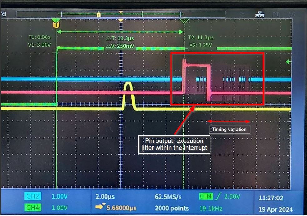
In my application running on a MK20DX256VLK10 there are several interrupts. One is a rising edge external interrupt set to maximum priority. The other interrupts are set to medium. Inside the external interrupt is some code (see attached) to set a discrete out, wait then clear the discrete out. What I can see is that the discrete pulse (red) is occurring approx 11.3us after the rising edge signal triggering the interrupt (green) and also that the time varies up to about 4us (location of trailing edge of red pulse).
When the if conditional is uncommented so the code inside the interrupt executes periodically (every 1s) then there is additional variability in the time to service the interrupt.
What is causing the 4us servicing variability?
Why is the interrupt serviced approx 11.3us after the edge input trigger source?
Thanks!


- Mark as New
- Bookmark
- Subscribe
- Mute
- Subscribe to RSS Feed
- Permalink
- Report Inappropriate Content
Is there another way using the CPU peripherals that this objective could be achieved without depending on a software interrupt routine?
Can a timer be initialized to be enabled on the rising edge of a pin input (green trace) and then trigger a pin output (pink trace) or ADC conversion a specified amount of time (on the order of 1-2us with 100ns precision) after the rising edge pin input? The objective being to time the setting of an output pulse (pink trace) precisely with respect to the input pulse.
- Mark as New
- Bookmark
- Subscribe
- Mute
- Subscribe to RSS Feed
- Permalink
- Report Inappropriate Content
Hi,
I suppose that you can use the FTM to implement the scheme. An external trigger signal can be a synchronization signal, which can reinitialize the FTM counter to zero, and the FTM counter counts the tick from zero, the FTM can output PWM signal.,which can be the output signal.
Pls refer to section 3.11.4. Updating the FTM register with hardware control of AN5142.pdf, which I attached.
Hope it can help you
BR
XiangJun Rong
- Mark as New
- Bookmark
- Subscribe
- Mute
- Subscribe to RSS Feed
- Permalink
- Report Inappropriate Content
Thanks for the information.
However I'm most concerned not with interrupt latency but with the execution jitter within the interrupt. The latency appears to be mostly fixed. The timing jitter setting the discrete output is the problem.
The requirement is to set the discrete output a specified amount of time (Xus +/- 0.25us) after the rising edge of the green trace. So an event interrupt is triggered on the green rising edge and code to set the discrete out is executed from within the interrupt. However there is significant timing jitter setting this discrete.
How to reduce greatly or eliminate this jitter?
- Mark as New
- Bookmark
- Subscribe
- Mute
- Subscribe to RSS Feed
- Permalink
- Report Inappropriate Content
Hi,
For the interrupt jitter for each pin interrupt, the interrupt latency is dependent on the where the core executes when the interrupt happens. If it executes the code in main or the subroutine, the core will jump to the ISR immediately after pushing the predefined registers to stack. If it executes the code in the other ISR, as you know that cortex-M4 supports nested interrupt, the core will check the priority group bits, if the current interrupt has higher priority, the core will jump to the current ISR after pushing the predefined registers to stack. BTW, if the the core execute the atomic operation, the core will jump to ISR after the current atomic operation has finished.
In conclusion, pls configure the pin interrupt priority level to 0x00, which is the highest interrupt priority. Set the other module interrupt priority level as for example 0xF0, which is the lowest interrupt priority so that the Port pin interrupt can preempt the other interrupt.
Hope it can help you
BR
XiangJun Rong

- Mark as New
- Bookmark
- Subscribe
- Mute
- Subscribe to RSS Feed
- Permalink
- Report Inappropriate Content
Hi,
It is hard to know for sure what the timing error is. The green trace is the pin input that triggers the interrupt. The pink trace is the pin output set from within the interrupt. So either there is latency jitter of the interrupt being serviced or there is execution jitter within the interrupt. When the original scope shot was taken, the pin input interrupt was already set to highest priority (0x00). All other interrupts are set to medium.
Any other things to track down to eliminate the jitter? I would think it should be possible to have the pin output set a fixed amount of time from the pin input.
- Mark as New
- Bookmark
- Subscribe
- Mute
- Subscribe to RSS Feed
- Permalink
- Report Inappropriate Content
Hi,
Regarding the Jitter of interrupt, it is difficult to track down and get the reason.
Pls try to check the following items.
1)set the core at 120MHz which can reduce the interrupt latency.
2)pls try to disable all the other interrupt, just enable pin interrupt, use the simple code in the main() so that the core can jump to ISR without executing the atomic instruction.
void main(void)
{
.....
while(1)
{
__asm("nop");
__asm("nop");
__asm("nop");
__asm("nop");
__asm("nop");
__asm("nop");
}
}
Hope it can help you
BR
XiangJun Rong
- Mark as New
- Bookmark
- Subscribe
- Mute
- Subscribe to RSS Feed
- Permalink
- Report Inappropriate Content
Hi,
Pls refer to the AN12078.pdf, which focuses on the interrupt latency based on ARM Cortex-Mx core.
The K20 uses Cortex-M4 core, the i.mxrt10xx uses Cortex-M7 core, they have similar features.
https://www.nxp.com.cn/docs/en/application-note/AN12078.pdf
Hope it can help you
BR
XiangJun Rong