
- Forums
- Product Forums
- General Purpose MicrocontrollersGeneral Purpose Microcontrollers
- i.MX Forumsi.MX Forums
- QorIQ Processing PlatformsQorIQ Processing Platforms
- Identification and SecurityIdentification and Security
- Power ManagementPower Management
- Wireless ConnectivityWireless Connectivity
- RFID / NFCRFID / NFC
- Advanced AnalogAdvanced Analog
- Neural Processing UnitsNeural Processing Units
- MCX Microcontrollers
- S32G
- S32K
- S32V
- MPC5xxx
- Other NXP Products
- S12 / MagniV Microcontrollers
- Powertrain and Electrification Analog Drivers
- Sensors
- Vybrid Processors
- Digital Signal Controllers
- 8-bit Microcontrollers
- ColdFire/68K Microcontrollers and Processors
- PowerQUICC Processors
- OSBDM and TBDML
- S32M
- S32Z/E
-
- Solution Forums
- Software Forums
- MCUXpresso Software and ToolsMCUXpresso Software and Tools
- CodeWarriorCodeWarrior
- MQX Software SolutionsMQX Software Solutions
- Model-Based Design Toolbox (MBDT)Model-Based Design Toolbox (MBDT)
- FreeMASTER
- eIQ Machine Learning Software
- Embedded Software and Tools Clinic
- S32 SDK
- S32 Design Studio
- GUI Guider
- Zephyr Project
- Voice Technology
- Application Software Packs
- Secure Provisioning SDK (SPSDK)
- Processor Expert Software
- Generative AI & LLMs
-
- Topics
- Mobile Robotics - Drones and RoversMobile Robotics - Drones and Rovers
- NXP Training ContentNXP Training Content
- University ProgramsUniversity Programs
- Rapid IoT
- NXP Designs
- SafeAssure-Community
- OSS Security & Maintenance
- Using Our Community
-
- Cloud Lab Forums
-
- Knowledge Bases
- ARM Microcontrollers
- i.MX Processors
- Identification and Security
- Model-Based Design Toolbox (MBDT)
- QorIQ Processing Platforms
- S32 Automotive Processing Platform
- Wireless Connectivity
- CodeWarrior
- MCUXpresso Suite of Software and Tools
- MQX Software Solutions
- RFID / NFC
- Advanced Analog
- Neural Processing Units
-
- NXP Tech Blogs
- Home
- :
- General Purpose Microcontrollers
- :
- Kinetis Microcontrollers
- :
- Re: Can't program new KL2 devices with ulink2 and uvision
Can't program new KL2 devices with ulink2 and uvision
- Subscribe to RSS Feed
- Mark Topic as New
- Mark Topic as Read
- Float this Topic for Current User
- Bookmark
- Subscribe
- Mute
- Printer Friendly Page
- Mark as New
- Bookmark
- Subscribe
- Mute
- Subscribe to RSS Feed
- Permalink
- Report Inappropriate Content
I seem to be able to connect to any freescale board that's already been programmed, like the 10-pin SWD connector on the Freedom board. But I have a custom board with a 10k pull-up and 10nF cap on the reset. Upon flashing, erasing, or debugging I get "SWD Communications Failure". On my board I notice that the reset line is oscillating. Reading previous posts an FAE reported that this is expected behavior on new devices since the flash is initialized to all 0xFF. Here's the things I've tried:
- with and without 10k pull-up on SWDIO
- 10nF, 1uF and no capacitor on bRESET
- at least 10 new KL25Z128VFM4 devices
My schematic is identical to the Freedom board KL2 except that the KL2 is unprogrammed. Strangely at one point my board programmed and I was using it for a few hours. Then it stopped working and again I got a "SWD Communication Failure".
I've read through every post in this forum regarding Kinetis devices. It appears to be something about the KLx initial condition that prevents it from communicating. But I have yet to find a solution on the ulink2.
thank you,
Joel
Solved! Go to Solution.
- Mark as New
- Bookmark
- Subscribe
- Mute
- Subscribe to RSS Feed
- Permalink
- Report Inappropriate Content
Holy toledo! I finally have all the board JTAG SW working 100% reliably by adding 100pF to the SWCLK and SWDIO lines at the chip!!!!!! Wow, I never thought that would be the issue. It looks like the debug port is incredibly sensitive to ultra high frequency noise. By adding my finger in the vicinity of the SW lines I coupled enough of high frequency noise to ground to make SW error free.
Problem solved. Hopefully this will help others who use the KLxx devices, which other than this issue appear to be pretty awesome devices.
- Mark as New
- Bookmark
- Subscribe
- Mute
- Subscribe to RSS Feed
- Permalink
- Report Inappropriate Content
Hi Joel Brinton,
Would you please specify the Keil version that you are using? I am trying to reproduce the issue here.
Thanks for your patience!!
B.R
Kan
- Mark as New
- Bookmark
- Subscribe
- Mute
- Subscribe to RSS Feed
- Permalink
- Report Inappropriate Content
Hi Kan,
At this point I think we're calling it a solder reflow issue. We're using some pretty thin PCBs with the QFN-32 package which seems to be causing issues when it's handled.
Thanks for your reply.
Joel
- Mark as New
- Bookmark
- Subscribe
- Mute
- Subscribe to RSS Feed
- Permalink
- Report Inappropriate Content
Hi Joel,
That's great!! Please kindly let me know if you have any issue.
Have a good day!!
B.R
Kan
- Mark as New
- Bookmark
- Subscribe
- Mute
- Subscribe to RSS Feed
- Permalink
- Report Inappropriate Content
Hi Kan,
We just made 35 new boards and they all have the same problem. I think we have a design issue. It seems to be though by placing a finger on the a number of the KL25 pins I am able to connection. This seems like some kind of pull-up/pull-down resistor or capacitor problem. We are at our wits end and desperately need help. Can you provide a schematic review?
Thank you kindly,
Joel
- Mark as New
- Bookmark
- Subscribe
- Mute
- Subscribe to RSS Feed
- Permalink
- Report Inappropriate Content
Hi Joel,
I have reviewed the schematics, it should be fine. Is there any progress on this issue with Vicente's suggestion?
B.R
Kan
- Mark as New
- Bookmark
- Subscribe
- Mute
- Subscribe to RSS Feed
- Permalink
- Report Inappropriate Content
Hi Kan, Dieter, Pedro,
The crystal is indeed oscillating at 26MHz. Per the datasheet I need at least 20pF. I also tried Dieter's suggestion of 60pF. I also added a load resistor per the App Note. Surprisingly it oscillated under all conditions.
Still, when I lightly touch seemingly random areas of the PCB I can program it. I'm trying to be a bit more precise and figure out exactly what conditions make it start, but nothing seems very reliable.
Perhaps I can send Freescale one of the boards to take a look at??? This behavior is completely reproducable across all of our boards. Are you in San Jose? I'm nearby, perhaps I can just come in and we can work the problem.
Thank you,
Joel
- Mark as New
- Bookmark
- Subscribe
- Mute
- Subscribe to RSS Feed
- Permalink
- Report Inappropriate Content
Hi Joel
have you try to touch up the device? I believe that you are using a QFN package, if this is the case in some times, the pads are not properly solder and is difficult inspect if the component, you can rework one of this component but be careful is also to easy make some solder short.
I hope this will help you.
Vicente Gomez
- Mark as New
- Bookmark
- Subscribe
- Mute
- Subscribe to RSS Feed
- Permalink
- Report Inappropriate Content
Holy toledo! I finally have all the board JTAG SW working 100% reliably by adding 100pF to the SWCLK and SWDIO lines at the chip!!!!!! Wow, I never thought that would be the issue. It looks like the debug port is incredibly sensitive to ultra high frequency noise. By adding my finger in the vicinity of the SW lines I coupled enough of high frequency noise to ground to make SW error free.
Problem solved. Hopefully this will help others who use the KLxx devices, which other than this issue appear to be pretty awesome devices.
- Mark as New
- Bookmark
- Subscribe
- Mute
- Subscribe to RSS Feed
- Permalink
- Report Inappropriate Content
Hi Vicente,
Yes, we have 30 devices all with the same behavior. On a number of devices I've tried reflowing the parts. We've also tried different solder stencil thicknesses. Our original assumption was that it was a solder problem. However, when I touch the board I'm very careful not to apply any pressure whatsoever to the QFN itself to eliminate the possibility that I'm closing a cold solder joint. When I touch various components I'm getting it to connect about 10% of the time.
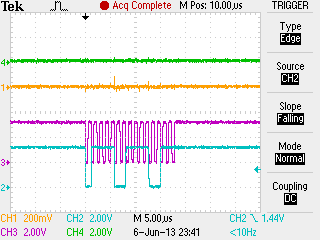
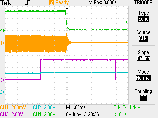
I've also verified with the crystal manufacturer that indeed the right parallel load capacitor value is 15pF. I've also measured that when the ULINK2 pulls down RESET# that the KL25 oscillator stops (by measuring at the crystal). See attached plot #1 and #2 for that measurement.
GREEN = RESET#
YELLOW = EXTAL0 (pin 18, PTA19)
PURPLE = SWCLK
BLUE = SWDIO
Interestingly it looks like the KL25 oscillator is not even running when SWCLK gives it's first set of pulses, plot #3 and #4.
It appears that there is some data on the SWDIO line after the first pulse, but I don't know how to interpret the particular Keil 2-wire JTAG SWD protocol.
Any insight and review of these plots is much appreciated.
Thank you,
Joel
- Mark as New
- Bookmark
- Subscribe
- Mute
- Subscribe to RSS Feed
- Permalink
- Report Inappropriate Content
As i tried to explain before, there is a factor 2 involved in the caps. 2x 30 pF caps in series result in a 15 pF load capacitance (disregarding stray caps). 2x 60 pF in series would give the 30 pF load capacitance, if the crystal was made for 30 pF load.
If the crystal gets turned on, the device got programmed before and i think your next step is preparing code that doesnt go astray and (almost) bricks your device. Hope you can use your "touch sensor" trick to get it inside the devices.
- Mark as New
- Bookmark
- Subscribe
- Mute
- Subscribe to RSS Feed
- Permalink
- Report Inappropriate Content
Hi Dieter,
thanks for the reply. The crystal datasheet recommends a 10pF load capacitor. Using the equation C_L = (C1 x C2) / (C1 + C2) + C_stray and then solving for C1=C2 I get ~15pF. I confirmed this value with NDK, the crystal manufacturer. The reason why the capacitance is so low for this frequency is that it's a fundamental crystal (not your normal 26MHz variety).
Currently my code is a while(1) { }. I've also flashed on the Freescale Freedom blinky.c application with the same results.
Joel
- Mark as New
- Bookmark
- Subscribe
- Mute
- Subscribe to RSS Feed
- Permalink
- Report Inappropriate Content
Looking at the schematic, i did not see any wiring for NMI_b.
- Mark as New
- Bookmark
- Subscribe
- Mute
- Subscribe to RSS Feed
- Permalink
- Report Inappropriate Content
Hi Dieter,
Thanks for looking at this. We did see this too, but I notice on the Freescale Freedom board that this pin is just floating. Also, in the KL25 Sub-Family Reference Manual I see that it has an internal pull-up on POR. If I'm to do something extra to this pin can you tell me what it is?
Kind regards,
Joel
- Mark as New
- Bookmark
- Subscribe
- Mute
- Subscribe to RSS Feed
- Permalink
- Report Inappropriate Content
The MKL25 is already programmed? Have you check if the external oscillator is working? Probably when you touch the device the oscillator start to work, this can be due a problem on the feedback resistor or even the oscilator. you can check the application not AN3208
http://www.freescale.com/files/microcontrollers/doc/app_note/AN3208.pdf
I hope this will help you.
- Mark as New
- Bookmark
- Subscribe
- Mute
- Subscribe to RSS Feed
- Permalink
- Report Inappropriate Content
Yes, the 15pF caps on the crystal are wrong. A standard load spec for a high frequency crystal is 30pF. That means in order to get the correct frequency and a reliable phase inversion, you need 2 caps of 60pF each.