
- NXP Forums
- Product Forums
- General Purpose MicrocontrollersGeneral Purpose Microcontrollers
- i.MX Forumsi.MX Forums
- QorIQ Processing PlatformsQorIQ Processing Platforms
- Identification and SecurityIdentification and Security
- Power ManagementPower Management
- MCX Microcontrollers
- S32G
- S32K
- S32V
- MPC5xxx
- Other NXP Products
- Wireless Connectivity
- S12 / MagniV Microcontrollers
- Powertrain and Electrification Analog Drivers
- Sensors
- Vybrid Processors
- Digital Signal Controllers
- 8-bit Microcontrollers
- ColdFire/68K Microcontrollers and Processors
- PowerQUICC Processors
- OSBDM and TBDML
-
- Solution Forums
- Software Forums
- MCUXpresso Software and ToolsMCUXpresso Software and Tools
- CodeWarriorCodeWarrior
- MQX Software SolutionsMQX Software Solutions
- Model-Based Design Toolbox (MBDT)Model-Based Design Toolbox (MBDT)
- FreeMASTER
- eIQ Machine Learning Software
- Embedded Software and Tools Clinic
- S32 SDK
- S32 Design Studio
- Vigiles
- GUI Guider
- Zephyr Project
- Voice Technology
- Application Software Packs
- Secure Provisioning SDK (SPSDK)
- Processor Expert Software
-
- Topics
- Mobile Robotics - Drones and RoversMobile Robotics - Drones and Rovers
- NXP Training ContentNXP Training Content
- University ProgramsUniversity Programs
- Rapid IoT
- NXP Designs
- SafeAssure-Community
- OSS Security & Maintenance
- Using Our Community
-
- Cloud Lab Forums
-
- Home
- :
- MCUXpresso Software and Tools
- :
- LPCXpresso IDE
- :
- Own LPC1769 Board .. USB correct?
Own LPC1769 Board .. USB correct?
Turn on suggestions
Auto-suggest helps you quickly narrow down your search results by suggesting possible matches as you type.
Options
- Subscribe to RSS Feed
- Mark Topic as New
- Mark Topic as Read
- Float this Topic for Current User
- Bookmark
- Subscribe
- Mute
- Printer Friendly Page
Own LPC1769 Board .. USB correct?
06-15-2016
03:14 PM
1,195 Views
NXP Employee
- Mark as New
- Bookmark
- Subscribe
- Mute
- Subscribe to RSS Feed
- Permalink
- Report Inappropriate Content
Content originally posted in LPCWare by cell85 on Thu Sep 06 17:18:44 MST 2012
Hi,
I want to make my own Board. I wrote the Firmware already with my LPCXpresso 1769 after all checks, I'm now going to make my own dedicated Board (Smart Grid Energy Monitoring for selfmade Home-Solar Panels :)).
I wanted to ask if the USB is connected right? I wanted to use the usb as a VCOM.
VBUS from the USB PIN is connected to Pin 21 [P1.30] is this correct?
Is this necessary?
It would be glad if somebody could take a look (and maybe at the SWD too / JP1 is for direct LPCXpresso debugger connection) :)
WR
Sam
[ATTACH]827[/ATTACH]
12 Replies
06-15-2016
03:14 PM
1,132 Views
NXP Employee
- Mark as New
- Bookmark
- Subscribe
- Mute
- Subscribe to RSS Feed
- Permalink
- Report Inappropriate Content
Content originally posted in LPCWare by Ex-Zero on Fri Sep 07 19:42:42 MST 2012
Quote:
According to the http://www.keil.com/mcb1700/mcb1700-schematics.pdf
MCB1700 USB Device schematic (3-6) I added some Cap's and a 1Meg resistor for the USB ESD/EMI
:confused:
If you want to separate shield and GND, don't connect pin 5 of USB connector to shield :eek:
#1 R28 is a little bit high. 10k is a better choice.
#2 Q1 is switched without resistor. Add it or use a FET :)
06-15-2016
03:14 PM
1,132 Views
NXP Employee
- Mark as New
- Bookmark
- Subscribe
- Mute
- Subscribe to RSS Feed
- Permalink
- Report Inappropriate Content
Content originally posted in LPCWare by cell85 on Fri Sep 07 19:05:41 MST 2012
Yeah you're the Pro ;)
According to the http://www.keil.com/mcb1700/mcb1700-schematics.pdf
MCB1700 USB Device schematic (3-6) I added some Cap's and a 1Meg resistor for the USB ESD/EMI
And I removed the not necessary Pins for SWD
Here is the final editon of the schematic: http://www.mikrocontroller.net/attachment/154223/final_board.pdf
(1- Error in the schematic : the 200k resistor is now a 4u7F Cap)
WR
Sam
06-15-2016
03:14 PM
1,132 Views
NXP Employee
- Mark as New
- Bookmark
- Subscribe
- Mute
- Subscribe to RSS Feed
- Permalink
- Report Inappropriate Content
Content originally posted in LPCWare by Ex-Zero on Fri Sep 07 18:09:06 MST 2012
Thanks for the offer. Unfortunately my own CAN-controlled solar charger is working since about 10 years (now with LPC11C14) :)
Since my office and my cellar are full of my own prototypes I think you'll find a better usage for academic purpose...
Thanks for the offer. Unfortunately my own CAN-controlled solar charger is working since about 10 years (now with LPC11C14) :)
Since my office and my cellar are full of my own prototypes I think you'll find a better usage for academic purpose...
06-15-2016
03:14 PM
1,132 Views
NXP Employee
- Mark as New
- Bookmark
- Subscribe
- Mute
- Subscribe to RSS Feed
- Permalink
- Report Inappropriate Content
Content originally posted in LPCWare by cell85 on Fri Sep 07 16:52:54 MST 2012
Thank you :)
If you want I can send you an Prototype for helping me ... this is a pcb for my academic project, we gonna make some pieces :) .
Thats all I can offer :D
Thank you :)
If you want I can send you an Prototype for helping me ... this is a pcb for my academic project, we gonna make some pieces :) .
Thats all I can offer :D
06-15-2016
03:14 PM
1,132 Views
NXP Employee
- Mark as New
- Bookmark
- Subscribe
- Mute
- Subscribe to RSS Feed
- Permalink
- Report Inappropriate Content
Content originally posted in LPCWare by Ex-Zero on Fri Sep 07 16:44:53 MST 2012
Looks correct now.
#1 I usually don't connect JTAG-TDI (useless with SWD :rolleyes:)
#2 Also I don't connect 3.3V from LPC-Link to target board (target boards with higher current consumption can destroy LPC-Link) :)
Looks correct now.
#1 I usually don't connect JTAG-TDI (useless with SWD :rolleyes:)
#2 Also I don't connect 3.3V from LPC-Link to target board (target boards with higher current consumption can destroy LPC-Link) :)
06-15-2016
03:14 PM
1,132 Views
NXP Employee
- Mark as New
- Bookmark
- Subscribe
- Mute
- Subscribe to RSS Feed
- Permalink
- Report Inappropriate Content
Content originally posted in LPCWare by cell85 on Fri Sep 07 16:13:33 MST 2012
Quote: Zero
LPC-Link is SWD
Your connector is still incompatible, what's R27 there
EXT_POW is supplying LPC-Link 3.3V regulator to supply your target board, if LPC-Link is not powered by USB. That's not working with 3.3V.
Anyway, do you need to supply your self powered board via LPC-Link ?
Use the resistor to pull this pin up and the jumper to ground it (to switch to ISP, if necessary)
No I'm talking about your funny R12/R2 construction, which you are trying to sell as a 1k pullup
That's nonsense.
- sorry, I totally messed it up! -> Reset button corrected (I copied it from my old stm32 board the cap was against peaks while pressing..)
- now my device is self powered -> ext_pow removed.
- ISP Pin is now pulled up and can be grounded with some GND Pins around the Board.
Quote: Zero
LPC-Link is SWD
Your connector is still incompatible, what's R27 there
- Yes I know that it is SWD, thats why I deleted the second SWD connector.
- OK this is confusing me, I copied it from the LPC Docu
[ATTACH]831[/ATTACH]
(Bigger Picture: http://pic-upload.eu/index.php?Section=Picture&Action=ShowPicBig&p=7ee4a8a7eb190077b9e47c4174bc1fea)
Maybe you can tell me exact what is wrong or what I've to change :(
Thank you!
Quote: Zero
LPC-Link is SWD
Your connector is still incompatible, what's R27 there
EXT_POW is supplying LPC-Link 3.3V regulator to supply your target board, if LPC-Link is not powered by USB. That's not working with 3.3V.
Anyway, do you need to supply your self powered board via LPC-Link ?
Use the resistor to pull this pin up and the jumper to ground it (to switch to ISP, if necessary)
No I'm talking about your funny R12/R2 construction, which you are trying to sell as a 1k pullup
That's nonsense.
- sorry, I totally messed it up! -> Reset button corrected (I copied it from my old stm32 board the cap was against peaks while pressing..)
- now my device is self powered -> ext_pow removed.
- ISP Pin is now pulled up and can be grounded with some GND Pins around the Board.
Quote: Zero
LPC-Link is SWD
Your connector is still incompatible, what's R27 there
- Yes I know that it is SWD, thats why I deleted the second SWD connector.
- OK this is confusing me, I copied it from the LPC Docu
[ATTACH]831[/ATTACH]
(Bigger Picture: http://pic-upload.eu/index.php?Section=Picture&Action=ShowPicBig&p=7ee4a8a7eb190077b9e47c4174bc1fea)
Maybe you can tell me exact what is wrong or what I've to change :(
Thank you!
06-15-2016
03:14 PM
1,132 Views
NXP Employee
- Mark as New
- Bookmark
- Subscribe
- Mute
- Subscribe to RSS Feed
- Permalink
- Report Inappropriate Content
Content originally posted in LPCWare by Ex-Zero on Fri Sep 07 12:02:56 MST 2012
Quote:
- I kicked-out the SWD to use the LPC-Link connector for other Debuggers too.
Is it ok to connect EXT_POW with VIN (3,3V Regulator Input)
LPC-Link is SWD :eek:
Your connector is still incompatible, what's R27 there :confused:
EXT_POW is supplying LPC-Link 3.3V regulator to supply your target board, if LPC-Link is not powered by USB. That's not working with 3.3V.
Anyway, do you need to supply your self powered board via LPC-Link ?
Quote:
- ISP P2.10 is now pulled up with a jumper to 3V3 over 22k Resitor.
Use the resistor to pull this pin up and the jumper to ground it (to switch to ISP, if necessary) :)
Quote:
Sorry I didn't get you. You're talking about R12 right (1k resistor)?
No I'm talking about your funny R12/R2 construction, which you are trying to sell as a 1k pullup :confused:
Quote:
I now connected a12K Resistor near the LPC-Link NRESET Pin, this should be ok now right? Did you mean this?
That's nonsense.
Quote:
- I kicked-out the SWD to use the LPC-Link connector for other Debuggers too.
Is it ok to connect EXT_POW with VIN (3,3V Regulator Input)
LPC-Link is SWD :eek:
Your connector is still incompatible, what's R27 there :confused:
EXT_POW is supplying LPC-Link 3.3V regulator to supply your target board, if LPC-Link is not powered by USB. That's not working with 3.3V.
Anyway, do you need to supply your self powered board via LPC-Link ?
Quote:
- ISP P2.10 is now pulled up with a jumper to 3V3 over 22k Resitor.
Use the resistor to pull this pin up and the jumper to ground it (to switch to ISP, if necessary) :)
Quote:
Sorry I didn't get you. You're talking about R12 right (1k resistor)?
No I'm talking about your funny R12/R2 construction, which you are trying to sell as a 1k pullup :confused:
Quote:
I now connected a12K Resistor near the LPC-Link NRESET Pin, this should be ok now right? Did you mean this?
That's nonsense.
06-15-2016
03:14 PM
1,132 Views
NXP Employee
- Mark as New
- Bookmark
- Subscribe
- Mute
- Subscribe to RSS Feed
- Permalink
- Report Inappropriate Content
Content originally posted in LPCWare by cell85 on Fri Sep 07 10:31:35 MST 2012
- I spent a USB UP LED you're right, its a nice feature.
- XTAL2 ... ok didn't see that, I had still the old schematics on my pc.
- I kicked-out the SWD to use the LPC-Link connector for other Debuggers too.
Is it ok to connect EXT_POW with VIN (3,3V Regulator Input)
[ATTACH]830[/ATTACH]
- ISP P2.10 is now pulled up with a jumper to 3V3 over 22k Resitor.
Quote: Zero
Just copy LPCXpresso schematic again: R31 = 12k (or use 10k). Also a jumper can be useful to switch to ISP as described in UM10360 Chapter32:
What's R2 there? Pulldown :confused:
Values from 10k-47k are OK there.
Sorry I didn't get you. You're talking about R12 right (1k resistor)?
I now connected a12K Resistor near the LPC-Link NRESET Pin, this should be ok now right? Did you mean this?
Updated Schematics : http://www.mikrocontroller.net/attachment/154205/AiMS2000.pdf
WR Sam
06-15-2016
03:14 PM
1,132 Views
NXP Employee
- Mark as New
- Bookmark
- Subscribe
- Mute
- Subscribe to RSS Feed
- Permalink
- Report Inappropriate Content
Content originally posted in LPCWare by Ex-Zero on Fri Sep 07 07:35:57 MST 2012
Quote:
In other PCB designs, which are using this RTC too, there was no Resistor for RTC X2 connected. How much should it be ? I know it depends on the crystal
FC135:
http://www.epsondevice.com/docs/qd/e...et?id=ID000805
So what do you think why EA changed their schematic from old 1768 to new 1769 adding 100k :confused:
Quote:
I don't know about ISP Pullup, could you tell me where and how much?
Just copy LPCXpresso schematic again: R31 = 12k (or use 10k). Also a jumper can be useful to switch to ISP as described in UM10360 Chapter32:
Quote:
Pin P2.10 is used as a hardware request signal for ISP and therefore requires special attention. Since P2.10 is in high impedance mode after reset, it is important that the user
provides external hardware (a pull-up resistor or other device) to put the pin in a defined state. Otherwise unintended entry into ISP mode may occur.
Quote:
Isn't 1K enough ? how much should be the best?
What's R2 there? Pulldown :confused:
Values from 10k-47k are OK there.
Quote:
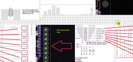
This should be 8-pin connector of the LPC-Link -> Target
I tried to copy this form Page 5-7 upper left corner
Again: This connector (J4) is described at Sheet 4/7 :mad:
Quote:
#7 No USB-UP LED?
#8 No USB-CONNECT LED?
No, I think I don't need it.
Working with USB without LED's, Good Luck :rolleyes:
Quote:
In other PCB designs, which are using this RTC too, there was no Resistor for RTC X2 connected. How much should it be ? I know it depends on the crystal
FC135:
http://www.epsondevice.com/docs/qd/e...et?id=ID000805
So what do you think why EA changed their schematic from old 1768 to new 1769 adding 100k :confused:
Quote:
I don't know about ISP Pullup, could you tell me where and how much?
Just copy LPCXpresso schematic again: R31 = 12k (or use 10k). Also a jumper can be useful to switch to ISP as described in UM10360 Chapter32:
Quote:
Pin P2.10 is used as a hardware request signal for ISP and therefore requires special attention. Since P2.10 is in high impedance mode after reset, it is important that the user
provides external hardware (a pull-up resistor or other device) to put the pin in a defined state. Otherwise unintended entry into ISP mode may occur.
Quote:
Isn't 1K enough ? how much should be the best?
What's R2 there? Pulldown :confused:
Values from 10k-47k are OK there.
Quote:
This should be 8-pin connector of the LPC-Link -> Target
I tried to copy this form Page 5-7 upper left corner
Again: This connector (J4) is described at Sheet 4/7 :mad:
Quote:
#7 No USB-UP LED?
#8 No USB-CONNECT LED?
No, I think I don't need it.
Working with USB without LED's, Good Luck :rolleyes:
06-15-2016
03:14 PM
1,132 Views
NXP Employee
- Mark as New
- Bookmark
- Subscribe
- Mute
- Subscribe to RSS Feed
- Permalink
- Report Inappropriate Content
Content originally posted in LPCWare by cell85 on Fri Sep 07 06:46:08 MST 2012
[U][B]Thank you Zero for you Tipps!
[/B][/U]
ok:
Quote: Zero
#1 No RTCX2 resistor?
In other PCB designs, which are using this RTC too, there was no Resistor for RTC X2 connected. How much should it be ? I know it depends on the crystal
FC135:
http://www.epsondevice.com/docs/qd/en/DownloadServlet?id=ID000805
Quote: Zero
#2 No ISP pullup :confused:
I don't know about ISP Pullup, could you tell me where and how much?
Quote: Zero
#3 Your Reset pullup is a little bit weak.
Isn't 1K enough ? how much should be the best?
Quote: Zero
#5 Don't know what JP1 is. If it's a 2.54mm connector (to be connected to LPCXpresso-J4) it's not pin compatible :confused:
This should be 8-pin connector of the LPC-Link -> Target
I tried to copy this form Page 5-7 upper left corner
(http://ics.nxp.com/support/documents/microcontrollers/pdf/lpcxpresso.lpc1769.schematic.pdf )
Quote: Zero
#6 Does Sheet 2-5 include a connector RxD0/TxD0 connector to rescue your board via FlashMagic :eek:
JP16 and JP17 are RX0 and TX0 (P0.2 & P0.3)
Quote: Zero
#7 No USB-UP LED?
#8 No USB-CONNECT LED?
No, I think I don't need it.
WR
Sam
06-15-2016
03:14 PM
1,132 Views
NXP Employee
- Mark as New
- Bookmark
- Subscribe
- Mute
- Subscribe to RSS Feed
- Permalink
- Report Inappropriate Content
Content originally posted in LPCWare by Ex-Zero on Thu Sep 06 20:46:46 MST 2012
Quote:
I wanted to ask if the USB is connected right? I wanted to use the usb as a VCOM.
It's a LPCXpresso copy, so why should it be wrong?
BTW: If you use a FET (BSS84) for switching D+, a resistor (your R17) isn't necessary.
Quote:
VBUS from the USB PIN is connected to Pin 21 [P1.30] is this correct?
Yes.
Quote:
Is this necessary?
No.
Quote:
It would be glad if somebody could take a look (and maybe at the SWD too / JP1 is for direct LPCXpresso debugger connection)
#1 No RTCX2 resistor?
#2 No ISP pullup :confused:
#3 Your Reset pullup is a little bit weak.
#4 SWD connector looks OK.
#5 Don't know what JP1 is. If it's a 2.54mm connector (to be connected to LPCXpresso-J4) it's not pin compatible :confused:
#6 Does Sheet 2-5 include a connector RxD0/TxD0 connector to rescue your board via FlashMagic :eek:
#7 No USB-UP LED?
#8 No USB-CONNECT LED?
Quote:
I wanted to ask if the USB is connected right? I wanted to use the usb as a VCOM.
It's a LPCXpresso copy, so why should it be wrong?
BTW: If you use a FET (BSS84) for switching D+, a resistor (your R17) isn't necessary.
Quote:
VBUS from the USB PIN is connected to Pin 21 [P1.30] is this correct?
Yes.
Quote:
Is this necessary?
No.
Quote:
It would be glad if somebody could take a look (and maybe at the SWD too / JP1 is for direct LPCXpresso debugger connection)
#1 No RTCX2 resistor?
#2 No ISP pullup :confused:
#3 Your Reset pullup is a little bit weak.
#4 SWD connector looks OK.
#5 Don't know what JP1 is. If it's a 2.54mm connector (to be connected to LPCXpresso-J4) it's not pin compatible :confused:
#6 Does Sheet 2-5 include a connector RxD0/TxD0 connector to rescue your board via FlashMagic :eek:
#7 No USB-UP LED?
#8 No USB-CONNECT LED?
06-15-2016
03:14 PM
1,132 Views
NXP Employee
- Mark as New
- Bookmark
- Subscribe
- Mute
- Subscribe to RSS Feed
- Permalink
- Report Inappropriate Content
Content originally posted in LPCWare by cell85 on Thu Sep 06 17:23:42 MST 2012
Here the hole Schematic for the MCU
http://www.mikrocontroller.net/attachment/154140/AiMS2000.pdf
Here the hole Schematic for the MCU
http://www.mikrocontroller.net/attachment/154140/AiMS2000.pdf