
- Forums
- Product Forums
- General Purpose MicrocontrollersGeneral Purpose Microcontrollers
- i.MX Forumsi.MX Forums
- QorIQ Processing PlatformsQorIQ Processing Platforms
- Identification and SecurityIdentification and Security
- Power ManagementPower Management
- Wireless ConnectivityWireless Connectivity
- RFID / NFCRFID / NFC
- Advanced AnalogAdvanced Analog
- Neural Processing UnitsNeural Processing Units
- MCX Microcontrollers
- S32G
- S32K
- S32V
- MPC5xxx
- Other NXP Products
- S12 / MagniV Microcontrollers
- Powertrain and Electrification Analog Drivers
- Sensors
- Vybrid Processors
- Digital Signal Controllers
- 8-bit Microcontrollers
- ColdFire/68K Microcontrollers and Processors
- PowerQUICC Processors
- OSBDM and TBDML
- S32M
- S32Z/E
-
- Solution Forums
- Software Forums
- MCUXpresso Software and ToolsMCUXpresso Software and Tools
- CodeWarriorCodeWarrior
- MQX Software SolutionsMQX Software Solutions
- Model-Based Design Toolbox (MBDT)Model-Based Design Toolbox (MBDT)
- FreeMASTER
- eIQ Machine Learning Software
- Embedded Software and Tools Clinic
- S32 SDK
- S32 Design Studio
- GUI Guider
- Zephyr Project
- Voice Technology
- Application Software Packs
- Secure Provisioning SDK (SPSDK)
- Processor Expert Software
- Generative AI & LLMs
-
- Topics
- Mobile Robotics - Drones and RoversMobile Robotics - Drones and Rovers
- NXP Training ContentNXP Training Content
- University ProgramsUniversity Programs
- Rapid IoT
- NXP Designs
- SafeAssure-Community
- OSS Security & Maintenance
- Using Our Community
-
- Cloud Lab Forums
-
- Knowledge Bases
- ARM Microcontrollers
- i.MX Processors
- Identification and Security
- Model-Based Design Toolbox (MBDT)
- QorIQ Processing Platforms
- S32 Automotive Processing Platform
- Wireless Connectivity
- CodeWarrior
- MCUXpresso Suite of Software and Tools
- MQX Software Solutions
- RFID / NFC
- Advanced Analog
- Neural Processing Units
-
- NXP Tech Blogs
- RSS フィードを購読する
- トピックを新着としてマーク
- トピックを既読としてマーク
- このトピックを現在のユーザーにフロートします
- ブックマーク
- 購読
- ミュート
- 印刷用ページ
Correct process to load code onto the M7
- 新着としてマーク
- ブックマーク
- 購読
- ミュート
- RSS フィードを購読する
- ハイライト
- 印刷
- 不適切なコンテンツを報告
Hi there,
I'm having trouble understanding the process of flashing code onto the Cortex-M7 of my S32G-VNP-RDB2. So far i've read substantial portions of the following documents:
- S32G-VNP-RDB2 User Guide
- S32G-VNP-RDB2 Reference Manual
- AN12422 S32G2 Boot Process
- S32G-VNP-RDB2 Software Enablement Guide
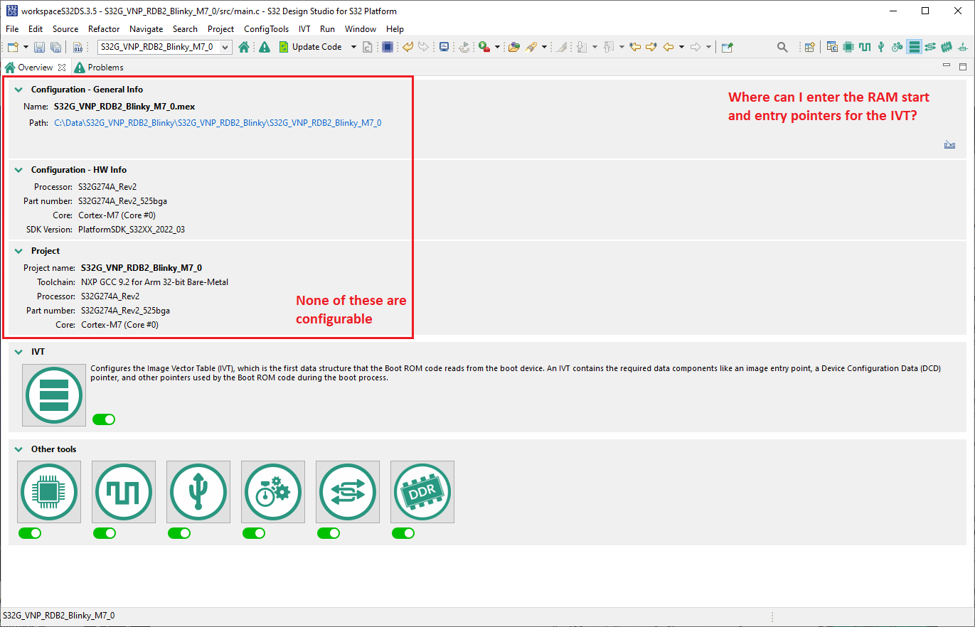
I've followed the SW-UG up to the section where i'm required to configure the IVT, but the images on the powerpoint and the available options on my S32 DS differ vastly ( See attached images ). This means i can't follow the guide correctly and so don't believe i should attempt to write to the SD card.
Currently, the SD card I received out the box is able to boot the CPU's and so I'm not sure whether i should be altering it or not. What would be very helpful would be a concise list of the exact steps required to flash the device - these preferably won't be specific to tools on S32 Design Studio as i'm required to use a different IDE and compiler for this project.
Below i'll outline my current understanding of the process, with any gaps of my knowledge:
- Compile code into .elf - this is required for debugging
- Create flash image as a .bin file
- Using memory values from linker script and .map file, construct the IVT according to Section 4.5.1 Image Vector Table ( AN12422 S32G2 Boot Process )*
- Write this image to the SD card using steps from Page 23 of S32G-VNP-RDB2 Software Enablement Guide and insert card into board*
- Setup UART connection on UART0 and open serial terminal on PC
- Configure the DIP switches on RDB2 for a SD card Boot ( Figure 3.3 - S32G-VNP-RDB2 User Guide ) and power on board - should see output on COMport
- Board should now be ready for debugging, I'm using the JTAG connector with a SEGGER J-link and i'll load the .elf file into a debug IDE e.g. SEGGER Ozone where I will be able to run the program(?)
*these are the steps that I'd particularly like more clarification on - are these required every time i flash the device? every time the code changes? every time i make linker script changes? in short when do i need to configure the IVT and write it onto the SD card?
There are quite likely mistakes in my process which hopefully someone will correct, and any help is greatly appreciated.
- 新着としてマーク
- ブックマーク
- 購読
- ミュート
- RSS フィードを購読する
- ハイライト
- 印刷
- 不適切なコンテンツを報告
Hi,
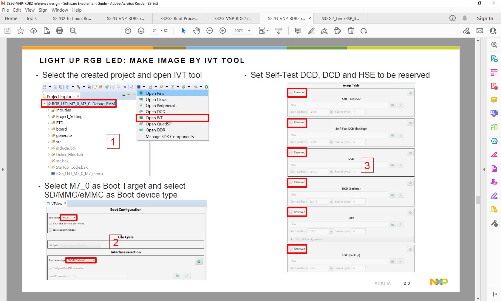
Regarding the IVT view issue you are seeing, it is related to (it seems) that the IVT view was closed prior to the project being loaded, hence you are not seeing the proper view. Below will be an image showing where to load the IVT view that the Software Enablement Guide is using.

As for the provided SD card with an image, you can modify it you want, since the Linux BSP is provided by NXP itself. If you want to load the Linux image you can download it from the "BSP for S32 Microcontrollers and Processors" product page (link: BSP for S32 MCUs and Processors | NXP Semiconductors) on the "Download" section.
As for the steps, we can provide the following comment:
- Regarding step 3, we recommend following the Software Enablement Guide's IVT structure.
- We don't completely understand the purpose of step 5 if you are following Software Enablement Guide
- Should be the same for step 6 regarding the COMport.
- SEGGER platform is not fully supported on S32G, meaning that the debugging could be not as easy as using either S32 Debug Probe or a Lauterbach. Still, could work.
Please, let us know.
- 新着としてマーク
- ブックマーク
- 購読
- ミュート
- RSS フィードを購読する
- ハイライト
- 印刷
- 不適切なコンテンツを報告
Hi Daniel,
Thank you for your reply, your fix for the missing IVT options was correct and i have now written to the SD card. Following the rest of the steps i can see the rgb LED turn on (if only very faintly).
I cannot debug this program at the moment, but i believe that is because there are extra steps i need to take to use the JTAG interface, I'll do some more research on this - we have some Lauterbach in-house but they are needed for other projects.
What would be great is more clarification on when i need to write to the SD card with this current method, and how that compares to the Linux BSP boot:
- I'm assuming that every time i edit code in the project, i will need to rewrite the SD card?
- As i'm only stating RAM pointers in the IVT, does this method prevent me from writing to the flash?
- If i load the linux BSP onto the SD card, will this allow me to load code directly onto the M7 e.g. through the debugger probe ? (i.e not having to load the boot config onto the SD every time)
I've had quick scan of the S32G LinuxBSP 33.0 User Manual but the only description i can see of the Linux BSP's purpose is the very short Introduction (Section 2). I'm new to this method of booting CPU(s) so any detail you can give will be very helpful.
Thanks again
- 新着としてマーク
- ブックマーク
- 購読
- ミュート
- RSS フィードを購読する
- ハイライト
- 印刷
- 不適切なコンテンツを報告
Hi,
Thanks for your feedback. Below will be some comments on regards of your open points:
- I'm assuming that every time I edit code in the project, I will need to rewrite the SD card?
If we are talking about the overall application, that is correct. If you modify something on the binary, you need to create another IVT structure and load it to the SD card (or to required boot interface).
This if there is no A/B update scheme developed by your side. If you have an A/B update scheme, then you should be able to update the image of the M7. Again, this only if you have an application that lets you update the running image on the M7. At this moment, there is no example available for this scheme from NXP side.
More on this topic is talked about in the AN12978 available on the S32G2 product page (link: S32G2 Safe and Secure Vehicle Network Processor | NXP Semiconductors)
- As i'm only stating RAM pointers in the IVT, does this method prevent me from writing to the flash?
The S32G platform does not implement an internal Flash. The only available memory inside the S32G platform is SRAM. You could write to an external flash if your code implements it.
- If i load the linux BSP onto the SD card, will this allow me to load code directly onto the M7 e.g. through the debugger probe ? (i.e not having to load the boot config onto the SD every time)
This may depend on when you are loading the image. We use the S32 Debug Probe. Since the probe we use halts all the cores of the platform, we cannot proceed how you are saying.
You could load from Linux BSP a binary into the M7 core, but many considerations are to be made since it could crash if either the linker or the configurations conflicts with u-boot/Linux.
We understand that you want to implement a multicore application. We can recommend looking into the AN13750 available on the S32G2 product page (link: S32G2 Safe and Secure Vehicle Network Processor | NXP Semiconductors) for more explanation on the multicore topic.
Please, let us know.
- 新着としてマーク
- ブックマーク
- 購読
- ミュート
- RSS フィードを購読する
- ハイライト
- 印刷
- 不適切なコンテンツを報告
Hi again Daniel, thank you for your clarifications they have been very helpful.
I'm actually not wanting to write a multi-core project, i have no intention of using the Cortex-A53's if i can help it. But if I can/must use them to boot the Cortex-M4 via the Linux BSP then that was my aim.
In a previous project (not NXP but similar u-boot process) the Linux Kernel would boot and then i was presented with a console with which i could configure a Cortex-R7 to be flashed over a debugger probe. Are you aware of any Linux commands which allow me to configure the M7 to be flashed via a probe on the RDB2?
____________________________________________________________________________
setenv resumer7 'mw E618024C 00000001 1; md E6153040 1; md E6180240 1;'
setenv unreset7 'mw E6150948 400000; md E61500B0 1; mw F0100000 1; mw F0100F80 1;'
setenv setr7 'run bar7; run resumer7; run unreset7;'
saveenv
____________________________________________________________________________
These commands allowed me to enable the Cortex-R7 to be flashed via the debug probe. I understand the architectures may be very different, but the attached image showing the Linux BSP running makes it look like it may be possible to do something similar with the RDB2?
I've read through the Linux BSP 33.0 User Manual for S32G2 platforms and AN12422 - S32G2 Boot Process documents and both hint that it may be possible, neither give explicit instructions.
Thanks again for all your help
- 新着としてマーク
- ブックマーク
- 購読
- ミュート
- RSS フィードを購読する
- ハイライト
- 印刷
- 不適切なコンテンツを報告
Hi,
Thanks for your feedback. As if you can, it is possible to boot M7 core from u-boot, there is even a command that lets you start the M7 core from u-boot:
"startm7 - start CM7_0 core from SRAM address"
As for instructions, there is no guide on how to build applications in order to load them through u-boot. We apologize. There is one example provided on the IPCF package that shows how to load an application from u-boot (the instructions are provided on the "description.txt" file available on the example), which is the only "guide" available for it.
Care should be taken to not re-initialize or modify modules being used by u-boot/Linux or overlap the memory space since it could crash the A53 application.
The HOW-TO of loading an image to the M7 core is mainly documented through the IVT structure, which can be written either to the NOR Flash or SD/eMMC. The IVT structure process is the one you have followed on the "Software Enablement Guide".
Also, this is how the multicore application (even if you are planning on using only the M7_0, M7_1 and M7_2 cores and not the A53 ones) is being implemented, modifying the NXP provided bootloader then flashing it using the IVT structure to the external NOR Flash.
Please, let us know if we have missed anything on our response.