
- NXP Forums
- Product Forums
- General Purpose MicrocontrollersGeneral Purpose Microcontrollers
- i.MX Forumsi.MX Forums
- QorIQ Processing PlatformsQorIQ Processing Platforms
- Identification and SecurityIdentification and Security
- Power ManagementPower Management
- MCX Microcontrollers
- S32G
- S32K
- S32V
- MPC5xxx
- Other NXP Products
- Wireless Connectivity
- S12 / MagniV Microcontrollers
- Powertrain and Electrification Analog Drivers
- Sensors
- Vybrid Processors
- Digital Signal Controllers
- 8-bit Microcontrollers
- ColdFire/68K Microcontrollers and Processors
- PowerQUICC Processors
- OSBDM and TBDML
-
- Solution Forums
- Software Forums
- MCUXpresso Software and ToolsMCUXpresso Software and Tools
- CodeWarriorCodeWarrior
- MQX Software SolutionsMQX Software Solutions
- Model-Based Design Toolbox (MBDT)Model-Based Design Toolbox (MBDT)
- FreeMASTER
- eIQ Machine Learning Software
- Embedded Software and Tools Clinic
- S32 SDK
- S32 Design Studio
- GUI Guider
- Zephyr Project
- Voice Technology
- Application Software Packs
- Secure Provisioning SDK (SPSDK)
- Processor Expert Software
-
- Topics
- Mobile Robotics - Drones and RoversMobile Robotics - Drones and Rovers
- NXP Training ContentNXP Training Content
- University ProgramsUniversity Programs
- Rapid IoT
- NXP Designs
- SafeAssure-Community
- OSS Security & Maintenance
- Using Our Community
-
- Cloud Lab Forums
-
In studying the instructional video 'NFC Antenna Design'
https://www.nxp.com/design/training/nfc-antenna-design:TIP-NFC-ANTENNA-DESIGN
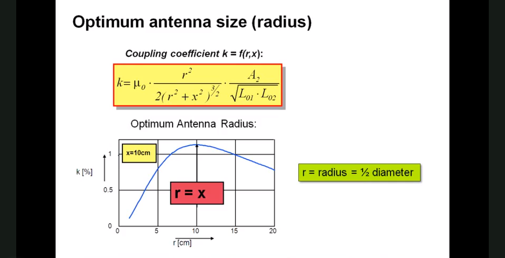
In terms of the discussion about the determination of optimum radius of RFID reader antenna in relation to distance (10cm) from the tag antenna (at approximately 0:18:19 in the video) and the formula for the coupling coefficient, the mathematics appears to me to indicate that the optimum occurs when the radius is equal to the square root of 2 multiplied by their relative distance (a little over 14cm as opposed to 10cm as the author states). Can anyone help me understand where I am misunderstanding the situation? I simply set the derivative of the formula with respect to r to zero and solved for r. See attached. Thanks.
已解决! 转到解答。
Hello @tedj1 ,
Yes, you are correct with the mathematics.
The missing part is L0 of the reader ("L01"): the "single turn" inductance increases with the increasing r. That "reduces the coupling at higher r".
a simple formula is used like this:

D = 2r = diameter of the antenna coil
d = wire diameter (= constant and small compared to D)
If you take this into account, the curve looks like plotted in the slides.
And in fact even in the curve result (as plotted in the slides), it can be seen that the maximum is not exactly at r=x, but slightly below... Still as a thumb rule it fits.
Have a great day,
Kan
-------------------------------------------------------------------------------
Note:
- If this post answers your question, please click the "Mark Correct" button. Thank you!
- We are following threads for 7 weeks after the last post, later replies are ignored
Please open a new thread and refer to the closed one, if you have a related question at a later point in time.
-------------------------------------------------------------------------------
Hello @tedj1 ,
Yes, you are correct with the mathematics.
The missing part is L0 of the reader ("L01"): the "single turn" inductance increases with the increasing r. That "reduces the coupling at higher r".
a simple formula is used like this:
D = 2r = diameter of the antenna coil
d = wire diameter (= constant and small compared to D)
If you take this into account, the curve looks like plotted in the slides.
And in fact even in the curve result (as plotted in the slides), it can be seen that the maximum is not exactly at r=x, but slightly below... Still as a thumb rule it fits.
Have a great day,
Kan
-------------------------------------------------------------------------------
Note:
- If this post answers your question, please click the "Mark Correct" button. Thank you!
- We are following threads for 7 weeks after the last post, later replies are ignored
Please open a new thread and refer to the closed one, if you have a related question at a later point in time.
-------------------------------------------------------------------------------