
- NXP Forums
- Product Forums
- General Purpose MicrocontrollersGeneral Purpose Microcontrollers
- i.MX Forumsi.MX Forums
- QorIQ Processing PlatformsQorIQ Processing Platforms
- Identification and SecurityIdentification and Security
- Power ManagementPower Management
- MCX Microcontrollers
- S32G
- S32K
- S32V
- MPC5xxx
- Other NXP Products
- Wireless Connectivity
- S12 / MagniV Microcontrollers
- Powertrain and Electrification Analog Drivers
- Sensors
- Vybrid Processors
- Digital Signal Controllers
- 8-bit Microcontrollers
- ColdFire/68K Microcontrollers and Processors
- PowerQUICC Processors
- OSBDM and TBDML
-
- Solution Forums
- Software Forums
- MCUXpresso Software and ToolsMCUXpresso Software and Tools
- CodeWarriorCodeWarrior
- MQX Software SolutionsMQX Software Solutions
- Model-Based Design Toolbox (MBDT)Model-Based Design Toolbox (MBDT)
- FreeMASTER
- eIQ Machine Learning Software
- Embedded Software and Tools Clinic
- S32 SDK
- S32 Design Studio
- Vigiles
- GUI Guider
- Zephyr Project
- Voice Technology
- Application Software Packs
- Secure Provisioning SDK (SPSDK)
- Processor Expert Software
-
- Topics
- Mobile Robotics - Drones and RoversMobile Robotics - Drones and Rovers
- NXP Training ContentNXP Training Content
- University ProgramsUniversity Programs
- Rapid IoT
- NXP Designs
- SafeAssure-Community
- OSS Security & Maintenance
- Using Our Community
-
- Cloud Lab Forums
-
- Home
- :
- Product Forums
- :
- MPC5xxx
- :
- [MPC5553] Can't Read Z-pulse of Encoder with eTPU QD function
[MPC5553] Can't Read Z-pulse of Encoder with eTPU QD function
- Subscribe to RSS Feed
- Mark Topic as New
- Mark Topic as Read
- Float this Topic for Current User
- Bookmark
- Subscribe
- Mute
- Printer Friendly Page
[MPC5553] Can't Read Z-pulse of Encoder with eTPU QD function
- Mark as New
- Bookmark
- Subscribe
- Mute
- Subscribe to RSS Feed
- Permalink
- Report Inappropriate Content
Hello. I have a question.
I have to use the qd function of eTPU for Encoder Signals
I used 10, 11, 12 channel of eTPU_A for A(primary), B(secondary), Z(index) pulse and c-files that compiled on NXP site.
The Result, Position Counter using A and B Pulse was increasing well. But the Revolution Counter wasn't increasing and Position Counter cannot be reset by Index(Z pulse).
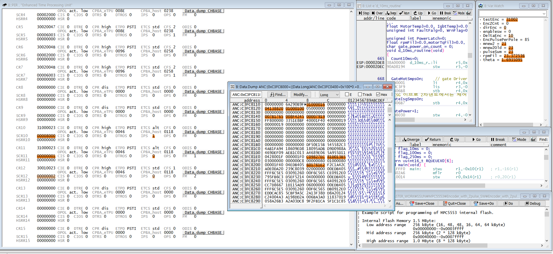
When I saw IPS bit of 12 channel using Trace32, IPS bit have correct behavior when the signal come in.
So, I saw the memory of RC and the value was zero.
I can't understand why it doesn't working well.
Please, Check my code.
etpu initializing function in etpu_gct.c
int32_t my_system_etpu_init()
{
int32_t err_code;
/* Initialization of eTPU global settings*/
fs_etpu_init( my_etpu_config, (uint32_t *)etpu_code, sizeof(etpu_code),
(uint32_t *)etpu_globals, sizeof(etpu_globals));
/* Initialization of eTPU channel settings*/
/* eTPU API Function initialization: 'QD - Quadrature Decoder'*/
err_code = fs_etpu_qd_init (QD0_PRIMARY, /* engine: A; channel: 10 */
ETPU_CHAN_NOT_USED, /* This channel is not used */
QD0_INDEX, /* engine: A; channel: 12 */
FS_ETPU_QD_PRIM_SEC_INDEX, /* Index, primary and secondary. */
FS_ETPU_PRIORITY_HIGH, /* priority: High */
FS_ETPU_QD_CONFIGURATION_1, /* configuration: Both QD pins are 1 when the INDEX is reached. */
FS_ETPU_TCR1, /* timer: FS_ETPU_TCR1 */
0, /* pc_max: 0 */
0, /* slow_normal_threshold: 0 */
0, /* normal_slow_threshold: 0 */
0, /* normal_fast_threshold: 0 */
0, /* fast_normal_threshold: 0 */
0, /* window_ratio1: 0 */
0, /* window_ratio2: 0 */
FS_ETPU_QD_HOME_TRANS_LOW_HIGH, /* home_transition: Detection of low-high transition. */
FS_ETPU_QD_INDEX_PULSE_POSITIVE, /* index_pulse: Index pulse of positive polarity. */
FS_ETPU_QD_INDEX_PC_RESET, /* index_pc_reset: Position Counter is reset on Index transition. */
FS_ETPU_QD_ETPU_A_TCR1_FREQ, /* etpu_tcr_freq: frequency of eTPU engine A - TCR1 */
256); /* pc_per_rev: 0 */
if (err_code != 0)
return ((QD0_PRIMARY) + 1);
And then I called this function in main.c
Next,
Channel is defined in etpu_gct.h
**************************************************************************/
#define QD0_PRIMARY ETPU_ENGINE_A_CHANNEL(10)
#define QD0_SECONDARY ETPU_ENGINE_A_CHANNEL(11)
#define QD0_INDEX ETPU_ENGINE_A_CHANNEL(12)
And etpu_qd_auto.h
/****************************************************************
* Function Configuration Information.
****************************************************************/
#define FS_ETPU_QD_FUNCTION_NUMBER 0
#define FS_ETPU_QD_TABLE_SELECT 1
#define FS_ETPU_QD_NUM_PARMS 0x0040
#define FS_ETPU_QD_INDEX_FUNCTION_NUMBER 1
#define FS_ETPU_QD_INDEX_TABLE_SELECT 0
#define FS_ETPU_QD_INDEX_NUM_PARMS 0x0040
/****************************************************************
* Host Service Request Definitions.
****************************************************************/
#define FS_ETPU_QD_INIT 1
#define FS_ETPU_QD_INDEX_INIT 1
And I used the API of qd function in main interrupt rountine.
if(enablesw)
{
fs_etpu_qd_enable(QD0_PRIMARY,
ETPU_CHAN_NOT_USED,
QD0_INDEX,
FS_ETPU_QD_PRIM_SEC_INDEX,
FS_ETPU_PRIORITY_HIGH);
enablesw = 0;
}
mnew2 = fs_etpu_qd_get_pc(QD0_PRIMARY);
dirEnc = fs_etpu_qd_get_direction(QD0_PRIMARY);
EncZCnt = fs_etpu_qd_get_rc(QD0_PRIMARY);
testEnc = fs_etpu_qd_get_pc_sc(QD0_PRIMARY);
And PCR register of 10,11,12 channels initialized in main.c
SIU.PCR[124].R = 0x0500; // Configure pad for signal ETPU_A[10] input
SIU.PCR[125].R = 0x0500; // Configure pad for signal ETPU_A[11] input
SIU.PCR[126].R = 0x0500; // Configure pad for signal ETPU_A[12] input
In addition, when I saw this project's behavior on Trace32, 'dirEnc' that have the direction information is toggle sometimes.
I attached a capture below.
I need help and I'll appreciate your help. Please.
Thank you.
Original Attachment has been moved to: Encoder_with_Zpulse_Example.zip
Original Attachment has been moved to: Example_PWM2Encoder_MPC5604.zip
- Mark as New
- Bookmark
- Subscribe
- Mute
- Subscribe to RSS Feed
- Permalink
- Report Inappropriate Content
I don’t see anything obvious. Do you have right configuration fitting to you sensor (I mean FS_ETPU_QD_CONFIGURATION_0/1) ?
- Mark as New
- Bookmark
- Subscribe
- Mute
- Subscribe to RSS Feed
- Permalink
- Report Inappropriate Content
Thanks to your comment :smileygrin:
Um... I think that's configuration is right.
I made the virtual signals using PWM of another board (TRK-MPC5604P). The signals have 25Hz, 0 to 5 [V], and 90 degree of phase difference. Z-pulse is recieved at once per 64 pulses (Both A and B have 64-pulses per 1 revolution). And Z-pulse is coming when A and B are high. I checked by oscilloscope.
I attached my test projects.
If you check my projects, I really appreciate.
Thanks.
- Mark as New
- Bookmark
- Subscribe
- Mute
- Subscribe to RSS Feed
- Permalink
- Report Inappropriate Content
I have tried to connect TRK-MPC5604P with your QD simulating software, but I dont see QD-like signal. You you only one phase toggling, you are changing the line by button.
Quadrature decoder in fact generates two signals like on the picture below:

Apparently you will have to modify the code on the TRK-MPC5604P side to have both lines toggling with different phases.
- Mark as New
- Bookmark
- Subscribe
- Mute
- Subscribe to RSS Feed
- Permalink
- Report Inappropriate Content
Thank your comment. But I think, there are right signals of phase A and B generated on TRK-MPC5604P.
void intc_U_Center(void)
{
FLEXPWM_0.SUB[0].STS.B.CMPF = 1;
SW=SIU.GPDI[48].R;
switch(SW)
{
case 1:
intcU_Ctr++;
if(intcU_Ctr>=64)
{
FLEXPWM_0.SUB[0].VAL[2].R = (unsigned short)-20000; // PWMA[0];PCR[58]-->rising ; phase A
FLEXPWM_0.SUB[0].VAL[3].R = (unsigned short) 0;//PWMA[0];PCR[58] --> falling ; phase A
FLEXPWM_0.SUB[0].VAL[4].R = (unsigned short)-10000;//PWMB[0];PCR[59]-->rising ; phase B
FLEXPWM_0.SUB[0].VAL[5].R = (unsigned short) 10000;//PWMB[0];PCR[58] --> falling ; phase B
FLEXPWM_0.SUB[1].VAL[2].R = (unsigned short)-10000;//PWMA[1];PCR[61]-->rising ; Generate Z pulse when intcU_Ctr is up to 64
FLEXPWM_0.SUB[1].VAL[3].R = (unsigned short) 0;//PWMA[1];PCR[61]-->falling
FLEXPWM_0.SUB[1].VAL[4].R = (unsigned short) 0;
FLEXPWM_0.SUB[1].VAL[5].R = (unsigned short) 0;
FLEXPWM_0.SUB[2].VAL[2].R = (unsigned short) 0;
FLEXPWM_0.SUB[2].VAL[3].R = (unsigned short) 0;
FLEXPWM_0.SUB[2].VAL[4].R = (unsigned short) 0;
FLEXPWM_0.SUB[2].VAL[5].R = (unsigned short) 0;
FLEXPWM_0.MCTRL.B.LDOK |= 0xF; // Load config values into buffers
FLEXPWM_0.MCTRL.B.RUN |=0xF; //1, 2, 3, 4 RUN
intcU_Ctr=0;
}
else
{
FLEXPWM_0.SUB[0].VAL[2].R = (unsigned short)-20000;// PWMA[0];PCR[58]-->rising
FLEXPWM_0.SUB[0].VAL[3].R = (unsigned short) 0;//PWMA[0];PCR[58] --> falling
FLEXPWM_0.SUB[0].VAL[4].R = (unsigned short)-10000;//PWMB[0];PCR[59]-->rising
FLEXPWM_0.SUB[0].VAL[5].R = (unsigned short) 10000;//PWMB[0];PCR[58] --> falling
FLEXPWM_0.SUB[1].VAL[2].R = (unsigned short) 0;
FLEXPWM_0.SUB[1].VAL[3].R = (unsigned short) 0;
FLEXPWM_0.SUB[1].VAL[4].R = (unsigned short) 0;
FLEXPWM_0.SUB[1].VAL[5].R = (unsigned short) 0;
FLEXPWM_0.SUB[2].VAL[2].R = (unsigned short) 0;
FLEXPWM_0.SUB[2].VAL[3].R = (unsigned short) 0;
FLEXPWM_0.SUB[2].VAL[4].R = (unsigned short) 0;
FLEXPWM_0.SUB[2].VAL[5].R = (unsigned short) 0;
FLEXPWM_0.MCTRL.B.LDOK |= 0xF; // Load config values into buffers
FLEXPWM_0.MCTRL.B.RUN |=0xF; //1, 2, 3, 4 RUN
}
break;
case 0: //And then, When I push the switch1, The direction of revolution is changed. So, Position Counter is decreasing and Revolution Counter is decreasing too. That means, phase B has a leading position.
intcU_Ctr--;
if(intcU_Ctr<=0)
{
FLEXPWM_0.SUB[0].VAL[2].R = (unsigned short)-10000;
FLEXPWM_0.SUB[0].VAL[3].R = (unsigned short) 10000;
FLEXPWM_0.SUB[0].VAL[4].R = (unsigned short)-20000;
FLEXPWM_0.SUB[0].VAL[5].R = (unsigned short) 0;
FLEXPWM_0.SUB[1].VAL[2].R = (unsigned short)-10000;
FLEXPWM_0.SUB[1].VAL[3].R = (unsigned short) 0;
FLEXPWM_0.SUB[1].VAL[4].R = (unsigned short) 0;
FLEXPWM_0.SUB[1].VAL[5].R = (unsigned short) 0;
FLEXPWM_0.SUB[2].VAL[2].R = (unsigned short) 0;
FLEXPWM_0.SUB[2].VAL[3].R = (unsigned short) 0;
FLEXPWM_0.SUB[2].VAL[4].R = (unsigned short) 0;
FLEXPWM_0.SUB[2].VAL[5].R = (unsigned short) 0;
FLEXPWM_0.MCTRL.B.LDOK |= 0xF; // Load config values into buffers
FLEXPWM_0.MCTRL.B.RUN |=0xF; //1, 2, 3, 4 RUN
intcU_Ctr=64;
}
else
{
FLEXPWM_0.SUB[0].VAL[2].R = (unsigned short)-10000;
FLEXPWM_0.SUB[0].VAL[3].R = (unsigned short) 10000;
FLEXPWM_0.SUB[0].VAL[4].R = (unsigned short)-20000;
FLEXPWM_0.SUB[0].VAL[5].R = (unsigned short) 0;
FLEXPWM_0.SUB[1].VAL[2].R = (unsigned short) 0;
FLEXPWM_0.SUB[1].VAL[3].R = (unsigned short) 0;
FLEXPWM_0.SUB[1].VAL[4].R = (unsigned short) 0;
FLEXPWM_0.SUB[1].VAL[5].R = (unsigned short) 0;
FLEXPWM_0.SUB[2].VAL[2].R = (unsigned short) 0;
FLEXPWM_0.SUB[2].VAL[3].R = (unsigned short) 0;
FLEXPWM_0.SUB[2].VAL[4].R = (unsigned short) 0;
FLEXPWM_0.SUB[2].VAL[5].R = (unsigned short) 0;
FLEXPWM_0.MCTRL.B.LDOK |= 0xF; // Load config values into buffers
FLEXPWM_0.MCTRL.B.RUN |=0xF; //1, 2, 3, 4 RUN
}
break;
}
}
What am I missing? I can't found it.
Thanks. ; )