
- Forums
- Product Forums
- General Purpose MicrocontrollersGeneral Purpose Microcontrollers
- i.MX Forumsi.MX Forums
- QorIQ Processing PlatformsQorIQ Processing Platforms
- Identification and SecurityIdentification and Security
- Power ManagementPower Management
- Wireless ConnectivityWireless Connectivity
- RFID / NFCRFID / NFC
- Advanced AnalogAdvanced Analog
- Neural Processing UnitsNeural Processing Units
- MCX Microcontrollers
- S32G
- S32K
- S32V
- MPC5xxx
- Other NXP Products
- S12 / MagniV Microcontrollers
- Powertrain and Electrification Analog Drivers
- Sensors
- Vybrid Processors
- Digital Signal Controllers
- 8-bit Microcontrollers
- ColdFire/68K Microcontrollers and Processors
- PowerQUICC Processors
- OSBDM and TBDML
- S32M
- S32Z/E
-
- Solution Forums
- Software Forums
- MCUXpresso Software and ToolsMCUXpresso Software and Tools
- CodeWarriorCodeWarrior
- MQX Software SolutionsMQX Software Solutions
- Model-Based Design Toolbox (MBDT)Model-Based Design Toolbox (MBDT)
- FreeMASTER
- eIQ Machine Learning Software
- Embedded Software and Tools Clinic
- S32 SDK
- S32 Design Studio
- GUI Guider
- Zephyr Project
- Voice Technology
- Application Software Packs
- Secure Provisioning SDK (SPSDK)
- Processor Expert Software
- Generative AI & LLMs
-
- Topics
- Mobile Robotics - Drones and RoversMobile Robotics - Drones and Rovers
- NXP Training ContentNXP Training Content
- University ProgramsUniversity Programs
- Rapid IoT
- NXP Designs
- SafeAssure-Community
- OSS Security & Maintenance
- Using Our Community
-
- Cloud Lab Forums
-
- Knowledge Bases
- ARM Microcontrollers
- i.MX Processors
- Identification and Security
- Model-Based Design Toolbox (MBDT)
- QorIQ Processing Platforms
- S32 Automotive Processing Platform
- Wireless Connectivity
- CodeWarrior
- MCUXpresso Suite of Software and Tools
- MQX Software Solutions
- RFID / NFC
- Advanced Analog
- Neural Processing Units
-
- NXP Tech Blogs
- Home
- :
- General Purpose Microcontrollers
- :
- LPC Microcontrollers
- :
- Re: LCP822 MCU programming problem using JLINK : error: * JLink Info: CPU did not halt after bootloa
LCP822 MCU programming problem using JLINK : error: * JLink Info: CPU did not halt after bootloader.
- Subscribe to RSS Feed
- Mark Topic as New
- Mark Topic as Read
- Float this Topic for Current User
- Bookmark
- Subscribe
- Mute
- Printer Friendly Page
- Mark as New
- Bookmark
- Subscribe
- Mute
- Subscribe to RSS Feed
- Permalink
- Report Inappropriate Content
Hi,
I'm using a LPC822 MCU for the below schematics but get an error while flashing:
Load "debug\\hello_world.out"
Set JLink Project File to "mdk\JLinkSettings.ini"
* JLink Info: Device "LPC822M101" selected.
JLink info:
------------
DLL: V7.56b, compiled Oct 18 2021 16:30:47
Firmware: J-Link ARM V8 compiled Nov 28 2014 13:44:46
Hardware: V8.00
S/N : 805251123
Feature(s) : RDI,FlashDL,FlashBP,JFlash,GDB
* JLink Info: Found SW-DP with ID 0x0BC11477
* JLink Info: DPv0 detected
* JLink Info: Scanning AP map to find all available APs
* JLink Info: AP[1]: Stopped AP scan as end of AP map has been reached
* JLink Info: AP[0]: AHB-AP (IDR: 0x04770031)
* JLink Info: Iterating through AP map to find AHB-AP to use
* JLink Info: AP[0]: Core found
* JLink Info: AP[0]: AHB-AP ROM base: 0xF0000000
* JLink Info: CPUID register: 0x410CC601. Implementer code: 0x41 (ARM)
* JLink Info: Found Cortex-M0 r0p1, Little endian.
* JLink Info: FPUnit: 4 code (BP) slots and 0 literal slots
* JLink Info: CoreSight components:
* JLink Info: ROMTbl[0] @ F0000000
* JLink Info: [0][0]: 14000000 CID 00000000 PID 00000000 ???
* JLink Info: [0][1]: E00FF000 CID B105100D PID 000BB4C0 ROM Table
* JLink Info: ROMTbl[1] @ E00FF000
* JLink Info: [1][0]: E000E000 CID B105E00D PID 000BB008 SCS
* JLink Info: [1][1]: E0001000 CID B105E00D PID 000BB00A DWT
* JLink Info: [1][2]: E0002000 CID B105E00D PID 000BB00B FPB
ROMTableAddr = 0xF0000000
* JLink Info: Reset: Halt core after reset via DEMCR.VC_CORERESET.
* JLink Info: Reset: Reset device via AIRCR.SYSRESETREQ.
* JLink Info: CPU did not halt after bootloader.
* JLink Info: CPU did not halt after bootloader.
Target info:
------------
Device: LPC822M101JHI33
VTarget = 3.293V
State of Pins:
TCK: 0, TDI: 0, TDO: 0, TMS: 1, TRES: 1, TRST: 1
Hardware-Breakpoints: 4
Software-Breakpoints: 8192
Watchpoints: 2
JTAG speed: 2000 kHz
Full Chip Erase Done.
Programming Done.
Verify OK.
* JLink Info: Reset: Halt core after reset via DEMCR.VC_CORERESET.
* JLink Info: Reset: Reset device via AIRCR.SYSRESETREQ.
* JLink Info: CPU did not halt after bootloader.
* JLink Info: CPU did not halt after bootloader.
Application running ...
Flash Load finished at 16:08:39
The application is not running after flash.
Thanks for your feedback.
Solved! Go to Solution.
.png)
- Mark as New
- Bookmark
- Subscribe
- Mute
- Subscribe to RSS Feed
- Permalink
- Report Inappropriate Content
Indeed the ISP pin was the problem. As P0_12 pin (ISP pin) was forced to the low mode by an external module so after reset the MCU was in BL mode. I think that on the LPC82X datasheet file figure 5 must be corrected and "PIO0_12/ISP" must be added to let the users pay attention to this pin while using it.
I released this pin and put a pullup resistor and the mcu worked normally.
Thanks for idea!
- Mark as New
- Bookmark
- Subscribe
- Mute
- Subscribe to RSS Feed
- Permalink
- Report Inappropriate Content
HI Elmar
Regarding to SWD interface design, please refer this FAQ
https://community.nxp.com/t5/LPCXpresso-IDE-FAQs/Design-Considerations-for-Debug/m-p/469565
To test the interface, please use MCUXpresso IDE to download SDK blinky led demo
Can the blinky code run on your target?
Thanks,
Jun Zhang
- Mark as New
- Bookmark
- Subscribe
- Mute
- Subscribe to RSS Feed
- Permalink
- Report Inappropriate Content
Thanks for your reply.
I can flash the device using stlink and jlink debuggers.
But I can't see the program application as for led blinky app the pin is not changing state.
So I tried to put the Keil into debug mode and the pointer goes through 3 instructions:
0x1FFF00D6 7830 LDRB r0,[r6,#0x00]
0x1FFF00D8 2800 CMP r0,#0x00
0x1FFF00DA D1FC BNE 0x1FFF00D6
Then it restart each time. And it loads them into R15(PC) Core (see attachment). That's all.
Any ideas?
- Mark as New
- Bookmark
- Subscribe
- Mute
- Subscribe to RSS Feed
- Permalink
- Report Inappropriate Content
Jlink IDE is 3rd and I don't have have. That's why I suggest you using MCUXpresso IDE to test the basic connection.
I suggest you follow attached video to test Jlink interface. If you can get the same result as the video, please use MCUXPresso IDE to test the download. MCUXpresso IDE is free. I am not compelling you changing IDE. This is only for the purpose to test the basic HW connection to identify the problem on your PC side or HW side.
Thanks
Jun Zhang
- Mark as New
- Bookmark
- Subscribe
- Mute
- Subscribe to RSS Feed
- Permalink
- Report Inappropriate Content
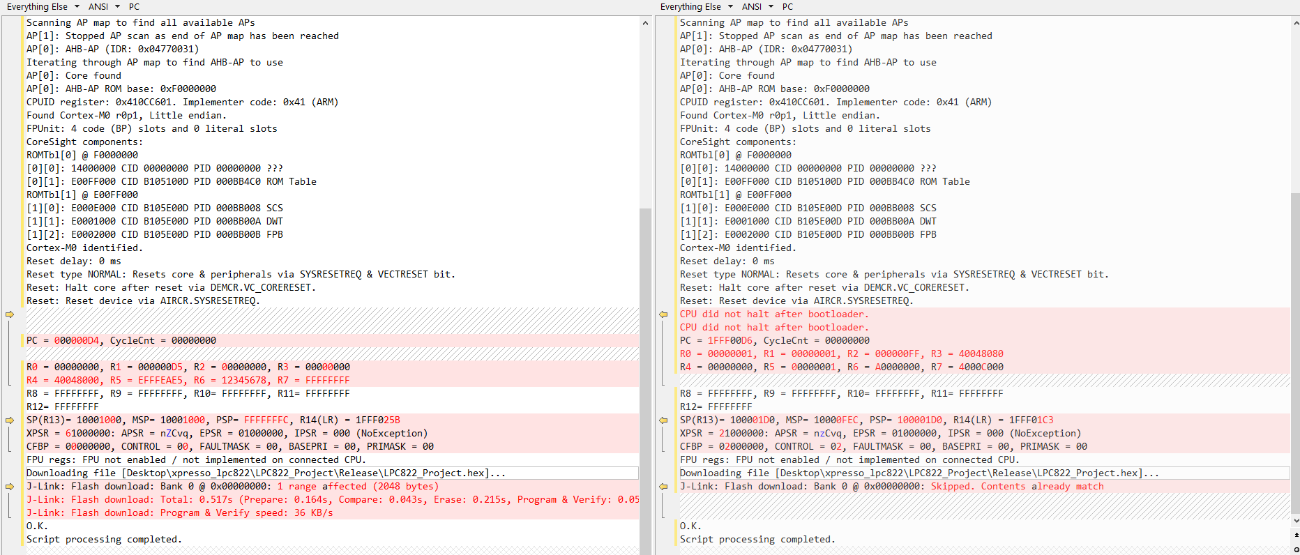
I used mcuxpresso id to put the 25th pin to 0.
I tested it on the 1st board that uses the same schematics and it worked, then used it on the 2nd board it didn't work. Both boards are the same LPC822M101 MCU.
Here is the comparison of the flashing messages (see attached) please.
Why it doesn't execute the program on my 2nd board?
- Mark as New
- Bookmark
- Subscribe
- Mute
- Subscribe to RSS Feed
- Permalink
- Report Inappropriate Content
Hi Elmar
For the second board, try to connect LPC822 in ISP mode. see how it works.
If fails, use Jlink commander to check if LPC822 core can be detected.
Jun Zhang
- Mark as New
- Bookmark
- Subscribe
- Mute
- Subscribe to RSS Feed
- Permalink
- Report Inappropriate Content
Indeed the ISP pin was the problem. As P0_12 pin (ISP pin) was forced to the low mode by an external module so after reset the MCU was in BL mode. I think that on the LPC82X datasheet file figure 5 must be corrected and "PIO0_12/ISP" must be added to let the users pay attention to this pin while using it.
I released this pin and put a pullup resistor and the mcu worked normally.
Thanks for idea!