
- Forums
- Product Forums
- General Purpose MicrocontrollersGeneral Purpose Microcontrollers
- i.MX Forumsi.MX Forums
- QorIQ Processing PlatformsQorIQ Processing Platforms
- Identification and SecurityIdentification and Security
- Power ManagementPower Management
- Wireless ConnectivityWireless Connectivity
- RFID / NFCRFID / NFC
- Advanced AnalogAdvanced Analog
- Neural Processing UnitsNeural Processing Units
- MCX Microcontrollers
- S32G
- S32K
- S32V
- MPC5xxx
- Other NXP Products
- S12 / MagniV Microcontrollers
- Powertrain and Electrification Analog Drivers
- Sensors
- Vybrid Processors
- Digital Signal Controllers
- 8-bit Microcontrollers
- ColdFire/68K Microcontrollers and Processors
- PowerQUICC Processors
- OSBDM and TBDML
- S32M
- S32Z/E
-
- Solution Forums
- Software Forums
- MCUXpresso Software and ToolsMCUXpresso Software and Tools
- CodeWarriorCodeWarrior
- MQX Software SolutionsMQX Software Solutions
- Model-Based Design Toolbox (MBDT)Model-Based Design Toolbox (MBDT)
- FreeMASTER
- eIQ Machine Learning Software
- Embedded Software and Tools Clinic
- S32 SDK
- S32 Design Studio
- GUI Guider
- Zephyr Project
- Voice Technology
- Application Software Packs
- Secure Provisioning SDK (SPSDK)
- Processor Expert Software
- Generative AI & LLMs
-
- Topics
- Mobile Robotics - Drones and RoversMobile Robotics - Drones and Rovers
- NXP Training ContentNXP Training Content
- University ProgramsUniversity Programs
- Rapid IoT
- NXP Designs
- SafeAssure-Community
- OSS Security & Maintenance
- Using Our Community
-
- Cloud Lab Forums
-
- Knowledge Bases
- ARM Microcontrollers
- i.MX Processors
- Identification and Security
- Model-Based Design Toolbox (MBDT)
- QorIQ Processing Platforms
- S32 Automotive Processing Platform
- Wireless Connectivity
- CodeWarrior
- MCUXpresso Suite of Software and Tools
- MQX Software Solutions
- RFID / NFC
- Advanced Analog
- Neural Processing Units
-
- NXP Tech Blogs
- Home
- :
- General Purpose Microcontrollers
- :
- LPC Microcontrollers
- :
- Having trouble reading pressure sensor using HS-SPI using LPC55S06-EVK
Having trouble reading pressure sensor using HS-SPI using LPC55S06-EVK
- Subscribe to RSS Feed
- Mark Topic as New
- Mark Topic as Read
- Float this Topic for Current User
- Bookmark
- Subscribe
- Mute
- Printer Friendly Page
Having trouble reading pressure sensor using HS-SPI using LPC55S06-EVK
- Mark as New
- Bookmark
- Subscribe
- Mute
- Subscribe to RSS Feed
- Permalink
- Report Inappropriate Content
Hello,
I am a novice just getting my hands into embedded systems for the first time so bare with me... I am tinkering around with pressure sensors, trying to read data using the SPI interface. I am struggling with reading data from the pressure sensor using the HS-SPI (High speed SPI) serial communication peripheral. I have ensured that all the SCK, MISO, PWR, GND, and CS pins have been connected correctly to the evaluation board. I imported one of the SDK examples (spi_HS_LSPI_dma_b2b_transfer_master) to try and read the pressure sensor. The only thing that I changed in the SDK example is the TRANSFER_SIZE variable from 64U to 2U because the size of the pressure data that is coming from the pressure sensor is only 2 bytes; however, when I run the example, the only thing getting printed is 0x00 0x00. I have included attachments of the datasheet for the pressure sensor that I am using as well as the code that I am using to try and read the pressure sensor.
Any help with resolving this issue would be appreciated. Additionally, if you have any sources/books/courses/etc. that you could recommend to me for getting into embedded systems/learning the MCUxpresso IDE I would appreciate that too! I'm just getting my foot in the door of this field trying to learn as much as I can.
Thank you!!
- Mark as New
- Bookmark
- Subscribe
- Mute
- Subscribe to RSS Feed
- Permalink
- Report Inappropriate Content
Hi,
If you want to use 16 bits data transfer, pls modify it as the following screenshot. Or in the main() to modify.
config->dataWidth = kSPI_Data16Bits; //kSPI_Data8Bits;
In the main():
SPI_MasterGetDefaultConfig(&masterConfig);
sourceClock = EXAMPLE_SPI_MASTER_CLK_FREQ;
masterConfig.sselNum = (spi_ssel_t)EXAMPLE_SPI_SSEL;
masterConfig.sselPol = (spi_spol_t)EXAMPLE_SPI_SPOL;
masterConfig.dataWidth=kSPI_Data16Bits;
SPI_MasterInit(EXAMPLE_SPI_MASTER, &masterConfig, sourceClock);

Hope it can help you
BR
XiangJun Rong
- Mark as New
- Bookmark
- Subscribe
- Mute
- Subscribe to RSS Feed
- Permalink
- Report Inappropriate Content
- Mark as New
- Bookmark
- Subscribe
- Mute
- Subscribe to RSS Feed
- Permalink
- Report Inappropriate Content
Short of reading your datasheet and your code myself ...
Are you sure the SPI settings are correct ?
SPI is not a fixed standard. Endianess, clock polarity and trigger edges may vary, and depend on the slave.
Some slave devices need special treatment. I recently had a device which nominally supported 16-bit transfers, but required a 60ns break between bytes, which required me to break it up into two byte transfers.
I would suggest to take a scope or logic analyzer, and compare your signals carefully with the requirements from the datasheet.
- Mark as New
- Bookmark
- Subscribe
- Mute
- Subscribe to RSS Feed
- Permalink
- Report Inappropriate Content
From reading the data sheet, it looks like the slave device will send out the most significant bits of the pressure data first, for clock polarity: the clock starts at a low state and becomes active on high, for clock phase: data is read on the clock's first edge, clock frequency should be set in between 50-800 KHz; I have it at 500 KHz. I set all of these in the SPI_MasterGetDefaultConfig function.
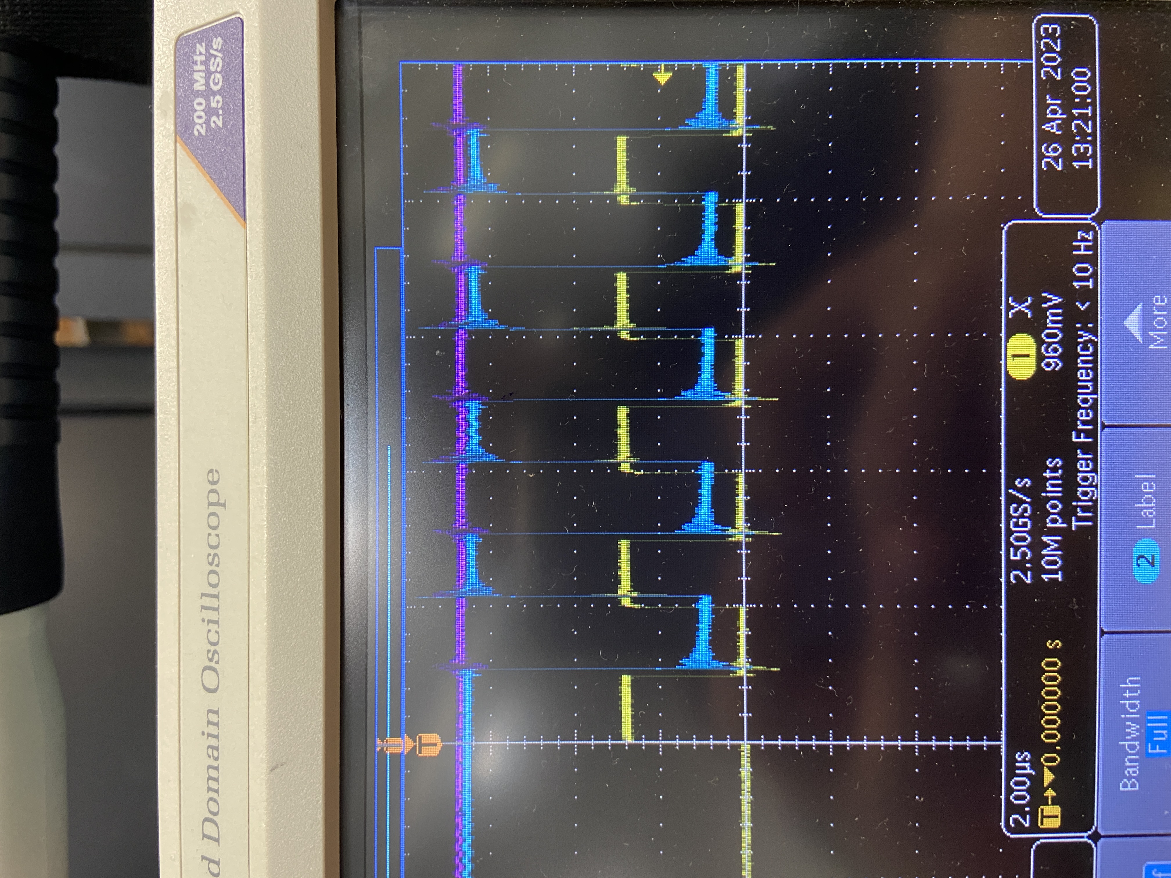
Attached to this response are images of readings from the oscilloscope. Something odd is that with the high-speed SPI that I'm trying to use, the chip select signal (in purple) never gets pulled down, also the clock signal (in yellow) only oscillates up to ~1.5V, and the MISO signal (in blue) just alternates between 1 and 0.
I ran an example using the "normal" SPI using FLEXCOMM3, and it was able to work just fine. If you look at the attached image, you can see the chip select signal getting pulled down, the clock oscillating from 0V to 3V, and the MISO signal producing reasonable signals besides just alternating between 1 and 0.
I do not know why the high-speed SPI signal is behaving in such an odd way.
- Mark as New
- Bookmark
- Subscribe
- Mute
- Subscribe to RSS Feed
- Permalink
- Report Inappropriate Content
Hi,
I suggest you connect the /CS, SCK and MISO signals to scope and check if there is output data from temperature sensor on the MISO pin.
Hope it can help you
BR
XiangJun Rong
- Mark as New
- Bookmark
- Subscribe
- Mute
- Subscribe to RSS Feed
- Permalink
- Report Inappropriate Content
Thank you!
- Mark as New
- Bookmark
- Subscribe
- Mute
- Subscribe to RSS Feed
- Permalink
- Report Inappropriate Content
Keep in mind that SPI is a digital signal, requiring about one order of magnitude higher bandwidth of the lines than the SCLK frequency. And you need to keep the wires/connections/PCB traces reasonable short.
Albeit below 1MHz, termination resistors are usually not necessary.
The wave shape of the "high-speed" SCLK signal looks ok, the amplitude not. But such an attenuation would be unreasonable below the specified clock limit.
Are you sure the scaling of the scope channels is the same ?
Have you checked the SS signal is correct, and does not assert before the transmission is complete ?