
- Forums
- Product Forums
- General Purpose MicrocontrollersGeneral Purpose Microcontrollers
- i.MX Forumsi.MX Forums
- QorIQ Processing PlatformsQorIQ Processing Platforms
- Identification and SecurityIdentification and Security
- Power ManagementPower Management
- Wireless ConnectivityWireless Connectivity
- RFID / NFCRFID / NFC
- Advanced AnalogAdvanced Analog
- Neural Processing UnitsNeural Processing Units
- MCX Microcontrollers
- S32G
- S32K
- S32V
- MPC5xxx
- Other NXP Products
- S12 / MagniV Microcontrollers
- Powertrain and Electrification Analog Drivers
- Sensors
- Vybrid Processors
- Digital Signal Controllers
- 8-bit Microcontrollers
- ColdFire/68K Microcontrollers and Processors
- PowerQUICC Processors
- OSBDM and TBDML
- S32M
- S32Z/E
-
- Solution Forums
- Software Forums
- MCUXpresso Software and ToolsMCUXpresso Software and Tools
- CodeWarriorCodeWarrior
- MQX Software SolutionsMQX Software Solutions
- Model-Based Design Toolbox (MBDT)Model-Based Design Toolbox (MBDT)
- FreeMASTER
- eIQ Machine Learning Software
- Embedded Software and Tools Clinic
- S32 SDK
- S32 Design Studio
- GUI Guider
- Zephyr Project
- Voice Technology
- Application Software Packs
- Secure Provisioning SDK (SPSDK)
- Processor Expert Software
- Generative AI & LLMs
-
- Topics
- Mobile Robotics - Drones and RoversMobile Robotics - Drones and Rovers
- NXP Training ContentNXP Training Content
- University ProgramsUniversity Programs
- Rapid IoT
- NXP Designs
- SafeAssure-Community
- OSS Security & Maintenance
- Using Our Community
-
- Cloud Lab Forums
-
- Knowledge Bases
- ARM Microcontrollers
- i.MX Processors
- Identification and Security
- Model-Based Design Toolbox (MBDT)
- QorIQ Processing Platforms
- S32 Automotive Processing Platform
- Wireless Connectivity
- CodeWarrior
- MCUXpresso Suite of Software and Tools
- MQX Software Solutions
- RFID / NFC
- Advanced Analog
- Neural Processing Units
-
- NXP Tech Blogs
- Home
- :
- 汎用マイクロコントローラ
- :
- LPCマイクロコントローラ
- :
- ADC in LPC 824
ADC in LPC 824
オプション
- RSS フィードを購読する
- トピックを新着としてマーク
- トピックを既読としてマーク
- このトピックを現在のユーザーにフロートします
- ブックマーク
- 購読
- ミュート
- 印刷用ページ
ADC in LPC 824
06-15-2016
01:09 PM
2,906件の閲覧回数
NXP Employee
- 新着としてマーク
- ブックマーク
- 購読
- ミュート
- RSS フィードを購読する
- ハイライト
- 印刷
- 不適切なコンテンツを報告
Content originally posted in LPCWare by krishna.mohan on Mon Oct 19 00:16:17 MST 2015
Hi,
I've downloaded the sample project from https://www.lpcware.com/content/nxpfile/lpcopen-software-development-platform-lpc8xx-packages.
and used the adc initialization code as shown below. ADC pins are 3, 9,10.
/* Setup ADC for 12-bit mode and normal power */
Chip_ADC_Init(LPC_ADC, 0);
/* Need to do a calibration after initialization and trim */
Chip_ADC_StartCalibration(LPC_ADC);
while (!(Chip_ADC_IsCalibrationDone(LPC_ADC))) {}
/* Setup for maximum ADC clock rate using sycnchronous clocking */
Chip_ADC_SetClockRate(LPC_ADC, ADC_MAX_SAMPLE_RATE);
/* Optionally, you can setup the ADC to use asycnchronous clocking mode.
To enable this, mode use 'LPC_ADC->CTRL |= ADC_CR_ASYNMODE;'.
In asycnchronous clocking mode mode, the following functions are
used to set and determine ADC rates:
Chip_Clock_SetADCASYNCSource();
Chip_Clock_SetADCASYNCClockDiv();
Chip_Clock_GetADCASYNCRate();
clkRate = Chip_Clock_GetADCASYNCRate() / Chip_Clock_GetADCASYNCClockDiv; */
/* Setup sequencer A for ADC channel 0, EOS interrupt */
//#if defined(BOARD_NXP_LPCXPRESSO_824)
/* Setup a sequencer to do the following:
Perform ADC conversion of ADC channels 0 only */
Chip_ADC_SetupSequencer(LPC_ADC, ADC_SEQA_IDX, (ADC_SEQ_CTRL_CHANSEL(3) | ADC_SEQ_CTRL_CHANSEL(9) |
ADC_SEQ_CTRL_CHANSEL(10) | ADC_SEQ_CTRL_MODE_EOS));
/* Enable the clock to the Switch Matrix */
Chip_Clock_EnablePeriphClock(SYSCTL_CLOCK_SWM);
/* Configure the SWM for P0-23 as the input for the ADC3 */
Chip_SWM_EnableFixedPin(SWM_FIXED_ADC3);
/* Configure the SWM for P0-17 as the input for the ADC9 */
Chip_SWM_EnableFixedPin(SWM_FIXED_ADC9);
/* Configure the SWM for P0-13 as the input for the ADC10 */
Chip_SWM_EnableFixedPin(SWM_FIXED_ADC10);
/* Disable the clock to the Switch Matrix to save power */
//Chip_Clock_DisablePeriphClock(SYSCTL_CLOCK_SWM);
//#else
//#warning "No ADC setup for this example"
//#endif
/* Setup threshold 0 low and high values to about 25% and 75% of max */
Chip_ADC_SetThrLowValue(LPC_ADC, 0, ((1 * 0xFFF) / 4));
Chip_ADC_SetThrHighValue(LPC_ADC, 0, ((3 * 0xFFF) / 4));
/* Clear all pending interrupts */
Chip_ADC_ClearFlags(LPC_ADC, Chip_ADC_GetFlags(LPC_ADC));
/* Enable ADC overrun and sequence A completion interrupts */
Chip_ADC_EnableInt(LPC_ADC, (ADC_INTEN_SEQA_ENABLE | ADC_INTEN_OVRRUN_ENABLE));
/* Use threshold 0 for ADC channel and enable threshold interrupt mode for
channel as crossing */
Chip_ADC_SelectTH0Channels(LPC_ADC, ADC_THRSEL_CHAN_SEL_THR1(BOARD_ADC_CH));
Chip_ADC_SetThresholdInt(LPC_ADC, BOARD_ADC_CH, ADC_INTEN_THCMP_CROSSING);
/* Enable ADC NVIC interrupt */
NVIC_EnableIRQ(ADC_SEQA_IRQn);
/* Enable sequencer */
Chip_ADC_EnableSequencer(LPC_ADC, ADC_SEQA_IDX);
And for reading the ADC result
rawSample = Chip_ADC_GetDataReg(LPC_ADC, 3);
adc_value = ADC_DR_RESULT(rawSample);
/* Show some ADC data */
if (rawSample & (ADC_DR_OVERRUN | ADC_SEQ_GDAT_DATAVALID)) {
putLineUART("Chan: 3 \r\n");
if(rawSample & ADC_DR_OVERRUN)
putLineUART("Overrun: True \r\n");
else
putLineUART("Overrun: False \r\n");
if(rawSample & ADC_SEQ_GDAT_DATAVALID)
putLineUART("Data Valid: True\r\n");
else
putLineUART("Data Valid: False\r\n");
}
rawSample = Chip_ADC_GetDataReg(LPC_ADC, 9);
adc_value = ADC_DR_RESULT(rawSample);
/* Show some ADC data */
if (rawSample & (ADC_DR_OVERRUN | ADC_SEQ_GDAT_DATAVALID)) {
putLineUART("Chan: 9 \r\n");
if(rawSample & ADC_DR_OVERRUN)
putLineUART("Overrun: True \r\n");
else
putLineUART("Overrun: False \r\n");
if(rawSample & ADC_SEQ_GDAT_DATAVALID)
putLineUART("Data Valid: True\r\n");
else
putLineUART("Data Valid: False\r\n");
}
rawSample = Chip_ADC_GetDataReg(LPC_ADC, 10);
adc_value = ADC_DR_RESULT(rawSample);
/* Show some ADC data */
if (rawSample & (ADC_DR_OVERRUN | ADC_SEQ_GDAT_DATAVALID)) {
putLineUART("Chan: 10 \r\n");
if(rawSample & ADC_DR_OVERRUN)
putLineUART("Overrun: True \r\n");
else
putLineUART("Overrun: False \r\n");
if(rawSample & ADC_SEQ_GDAT_DATAVALID)
putLineUART("Data Valid: True\r\n");
else
putLineUART("Data Valid: False\r\n");
}
All the adc results are showing the same result. Please let me know where is the mistake. I'm not figure it out.
Regards,
Krishnamohan.
2 返答(返信)
06-15-2016
01:09 PM
2,439件の閲覧回数
NXP Employee
- 新着としてマーク
- ブックマーク
- 購読
- ミュート
- RSS フィードを購読する
- ハイライト
- 印刷
- 不適切なコンテンツを報告
Content originally posted in LPCWare by krishna.mohan on Mon Oct 19 01:39:02 MST 2015
I've downloaded sample Project from https://www.lpcware.com/content/nxpfile/lpcopen-software-development-platform-lpc8xx-packages
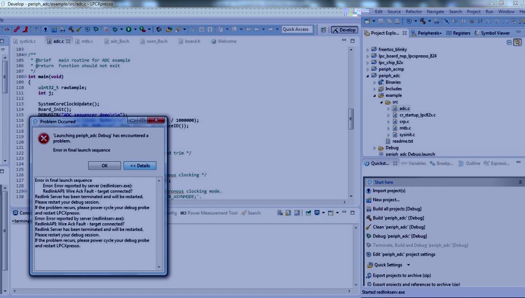
Build the periph_adc project in LPC Xpresso IDE. and tried to debug project though LPC-LINK2 debugger. it was prompting error window all the time even after restarting the LPC Xpresso.
Regards,
Krishnamohan
I've downloaded sample Project from https://www.lpcware.com/content/nxpfile/lpcopen-software-development-platform-lpc8xx-packages
Build the periph_adc project in LPC Xpresso IDE. and tried to debug project though LPC-LINK2 debugger. it was prompting error window all the time even after restarting the LPC Xpresso.
Regards,
Krishnamohan
06-15-2016
01:09 PM
2,439件の閲覧回数
NXP Employee
- 新着としてマーク
- ブックマーク
- 購読
- ミュート
- RSS フィードを購読する
- ハイライト
- 印刷
- 不適切なコンテンツを報告
Content originally posted in LPCWare by vtw.433e on Mon Oct 19 01:01:51 MST 2015
Debug the board, or debug an application running on the board?
See http://www.nxp.com/documents/user_manual/UM10830.pdf for details of the board (including how to connect a debugger)
Debug the board, or debug an application running on the board?
See http://www.nxp.com/documents/user_manual/UM10830.pdf for details of the board (including how to connect a debugger)