- NXP Forums
- Product Forums
- General Purpose MicrocontrollersGeneral Purpose Microcontrollers
- i.MX Forumsi.MX Forums
- QorIQ Processing PlatformsQorIQ Processing Platforms
- Identification and SecurityIdentification and Security
- Power ManagementPower Management
- MCX Microcontrollers
- S32G
- S32K
- S32V
- MPC5xxx
- Other NXP Products
- Wireless Connectivity
- S12 / MagniV Microcontrollers
- Powertrain and Electrification Analog Drivers
- Sensors
- Vybrid Processors
- Digital Signal Controllers
- 8-bit Microcontrollers
- ColdFire/68K Microcontrollers and Processors
- PowerQUICC Processors
- OSBDM and TBDML
-
- Solution Forums
- Software Forums
- MCUXpresso Software and ToolsMCUXpresso Software and Tools
- CodeWarriorCodeWarrior
- MQX Software SolutionsMQX Software Solutions
- Model-Based Design Toolbox (MBDT)Model-Based Design Toolbox (MBDT)
- FreeMASTER
- eIQ Machine Learning Software
- Embedded Software and Tools Clinic
- S32 SDK
- S32 Design Studio
- Vigiles
- GUI Guider
- Zephyr Project
- Voice Technology
- Application Software Packs
- Secure Provisioning SDK (SPSDK)
- Processor Expert Software
-
- Topics
- Mobile Robotics - Drones and RoversMobile Robotics - Drones and Rovers
- NXP Training ContentNXP Training Content
- University ProgramsUniversity Programs
- Rapid IoT
- NXP Designs
- SafeAssure-Community
- OSS Security & Maintenance
- Using Our Community
-
- Cloud Lab Forums
-
- Home
- :
- i.MX Forums
- :
- i.MX RT
- :
- Re: Trouble flashing custom board designed based on the 1020 Eval Kit
Trouble flashing custom board designed based on the 1020 Eval Kit
- Subscribe to RSS Feed
- Mark Topic as New
- Mark Topic as Read
- Float this Topic for Current User
- Bookmark
- Subscribe
- Mute
- Printer Friendly Page
- Mark as New
- Bookmark
- Subscribe
- Mute
- Subscribe to RSS Feed
- Permalink
- Report Inappropriate Content
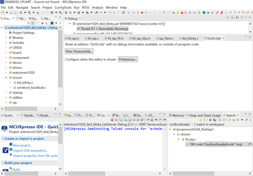
Hello, I am currently designing a board based on the 1020 Eval Kit. I having trouble flashing my custom board successfully. The program we are flashing is the PIT_timer example project. The board design is nearly identical to the Eval kit without additional components that I do need for my project and the MCU is MIMXRT1021CAG4A instead of MIMXRT1021DAG5A. For powering on and off the MCU, the VDD_SNVS_IN supply is connected (shorted) with the VDD_HIGH_IN supply. It is powered by supplying a 3.3 V. On idle when powering the MCU, all the pins for the boot mode are a low signal. Because the efuse is a low voltage signal, it should boot up the MCU in serial downloader mode. I used JTAG to flash the program. The screenshot below is what I see when trying to flash the program. In addition, I attached the schematic of my custom 1020 board. The file name is OBC SCHEMATIC. I was wondering what is causing the program not to flash successfully. It never goes to main. Thank you for all the help!
Solved! Go to Solution.
- Mark as New
- Bookmark
- Subscribe
- Mute
- Subscribe to RSS Feed
- Permalink
- Report Inappropriate Content
Thanks for your reply!
You can use UART, in this particular case the serial downloader supports LPUART 1 pins and you can specify the UART port setup with the MCU boot utility.
Therefore you can your use the MCU-Link as bridge
- Mark as New
- Bookmark
- Subscribe
- Mute
- Subscribe to RSS Feed
- Permalink
- Report Inappropriate Content
I hope you are doing great! my apologies for the delayed response.
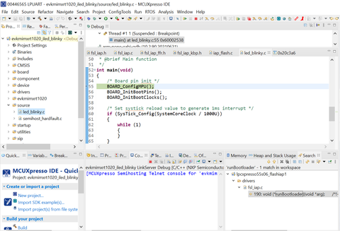
I was trying to replicate your issue , for instance I modified to boot from serial downloader mode my I.MX RT1020 EVK.
To be able to debug the application properly I just had to set to boot application from external flash, what corresponds to the serial downloader setup we have done.
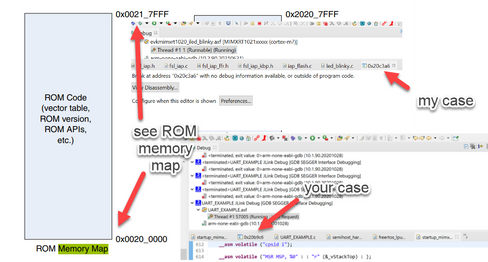
It seems that the program counter is at the BOOT ROM memory address.
So , as quick feedback , could you please try to debug when with the option to boot from external flash?
Let me know your results! and many thanks for your patience.
Diego
Edit > I missed that you said that you programmed a fuse, to get the board in serial downloader mode. In that case I think that you are not able to simple modify voltages externally as I did. Could you confirm?
- Mark as New
- Bookmark
- Subscribe
- Mute
- Subscribe to RSS Feed
- Permalink
- Report Inappropriate Content
Hello diego_charles, thank you for looking into this problem. The custom design of the board is fixed traces. What I mean by that is that the custom board does not have SW8 like the dev board to change the boot mode. I looked through the reference manual for the MCU and look at the schematics of the custom board to figure out what boot mode it would be. I used an oscilloscope to make sure the pins on the MCU are the signals I expected. Thus, I do not think I could simply modify the voltage externally,
Also, I will try to look into this problem tomorrow and get back to you about it regarding booting from external flash.
- Mark as New
- Bookmark
- Subscribe
- Mute
- Subscribe to RSS Feed
- Permalink
- Report Inappropriate Content
Hello @diego_charles,
I tried looking at options on how to use the external flash with how my custom board is set up. I tried using the MCUbootutility and jlink commander to reconfigure the MCU to boot with the external flash. However, I am new to this and was not able to figure out how to do that. With how my custom board is set up, is there a way I could configure the MCU to boot with the external flash? Also, would using the external flash be a problem for using a watchdog timer?
- Mark as New
- Bookmark
- Subscribe
- Mute
- Subscribe to RSS Feed
- Permalink
- Report Inappropriate Content
Thanks for your reply!
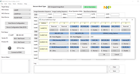
If you have the boot pins set to 00 and you want to avoid entering to serial downloader mode you will have to burn BT_FUSE_SEL as 1. Then, specify the boot config to boot from your memory option. That way you can boot from your external flash.
As you mention, the MCU boot utility will let you do this. Here is an snapshot showing the boot config 1 with the BT_FUSE_SEL.
Our colleague who made the utility gives a quick overview on the github page.
Also, with this you should be able to debug your application as expected. However the inconvenient that I can see is that if BT_FUSE_SEL is burned, you won't be able to enter serial downloader mode again.
The serial downloader mode can be used to regain debug access during development process. As a problematic image, that crashes the MCU, can be prevented from running be replaced by a good one. That is a reason why fuse burning is recommend for production stage.
Regarding the watchdog : I do not see any problem. You are using the same flash memory that the 1020 EVK uses a default boot option.
Let me know if you are still having inquiries that we could address.
Diego
- Mark as New
- Bookmark
- Subscribe
- Mute
- Subscribe to RSS Feed
- Permalink
- Report Inappropriate Content
Thanks that is really helpful! This makes a lot of sense. Currently, our OBC is designed to be only flashed with JTAG. Looking at the MCUbootutility, it seems like it is only designed for communicating through the USB connection. I was wondering how I could use a JTAG to blow the eFuse. If I cannot by JTAG, could I use the MCU Link to blow the eFuse through UART1 port? Also, is there any documentation on how I could do this through UART?
- Mark as New
- Bookmark
- Subscribe
- Mute
- Subscribe to RSS Feed
- Permalink
- Report Inappropriate Content
Thanks for your reply!
You can use UART, in this particular case the serial downloader supports LPUART 1 pins and you can specify the UART port setup with the MCU boot utility.
Therefore you can your use the MCU-Link as bridge


