
- NXP Forums
- Product Forums
- General Purpose MicrocontrollersGeneral Purpose Microcontrollers
- i.MX Forumsi.MX Forums
- QorIQ Processing PlatformsQorIQ Processing Platforms
- Identification and SecurityIdentification and Security
- Power ManagementPower Management
- MCX Microcontrollers
- S32G
- S32K
- S32V
- MPC5xxx
- Other NXP Products
- Wireless Connectivity
- S12 / MagniV Microcontrollers
- Powertrain and Electrification Analog Drivers
- Sensors
- Vybrid Processors
- Digital Signal Controllers
- 8-bit Microcontrollers
- ColdFire/68K Microcontrollers and Processors
- PowerQUICC Processors
- OSBDM and TBDML
-
- Solution Forums
- Software Forums
- MCUXpresso Software and ToolsMCUXpresso Software and Tools
- CodeWarriorCodeWarrior
- MQX Software SolutionsMQX Software Solutions
- Model-Based Design Toolbox (MBDT)Model-Based Design Toolbox (MBDT)
- FreeMASTER
- eIQ Machine Learning Software
- Embedded Software and Tools Clinic
- S32 SDK
- S32 Design Studio
- GUI Guider
- Zephyr Project
- Voice Technology
- Application Software Packs
- Secure Provisioning SDK (SPSDK)
- Processor Expert Software
-
- Topics
- Mobile Robotics - Drones and RoversMobile Robotics - Drones and Rovers
- NXP Training ContentNXP Training Content
- University ProgramsUniversity Programs
- Rapid IoT
- NXP Designs
- SafeAssure-Community
- OSS Security & Maintenance
- Using Our Community
-
- Cloud Lab Forums
-
- Home
- :
- i.MX Forums
- :
- i.MX RT
- :
- 回复: ADC_ETC CFG Problem
ADC_ETC CFG Problem
- Subscribe to RSS Feed
- Mark Topic as New
- Mark Topic as Read
- Float this Topic for Current User
- Bookmark
- Subscribe
- Mute
- Printer Friendly Page
- Mark as New
- Bookmark
- Subscribe
- Mute
- Subscribe to RSS Feed
- Permalink
- Report Inappropriate Content
HI:NXP Technical support
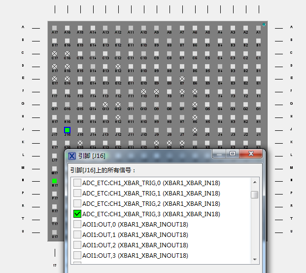
I need to consult you about the configuration of ADC_ETC. Now I want to configure an ADC to detect the battery voltage. I use RT1176 microcontroller, and the pin I use is GPIO_AD_34(J16), which has many reuse functions. Now I use the route IOMUXC_GPIO_AD_34_XBAR1_INOUT18, and enable the related configuration, but I find that it is possible to enter ADC interrupt, but read the data is always 0, so I suspect that there is something wrong with my configuration, but I can't find it, you can help me to let me know where the configuration is wrong. Nearby will give me my ADC
Here is my code:
#define DEMO_ADC_BASE LPADC1
#define DEMO_ADC_USER_CHANNEL 0U
#define DEMO_ADC_USER_CMDID 1U
#define DEMO_ADC_CHANNEL_GROUP 0U
#define DEMO_ADC_ETC_BASE ADC_ETC
#define DEMO_ADC_ETC_TRIGGER_GROUP 3U
#define DEMO_ADC_ETC_CHANNEL 1U
#define DEMO_ADC_ETC_DONE0_Handler ADC_ETC_IRQ0_IRQHandler
void ADC_ETC_Configuration(void)
{
adc_etc_config_t adcEtcConfig;
adc_etc_trigger_config_t adcEtcTriggerConfig;
adc_etc_trigger_chain_config_t adcEtcTriggerChainConfig;
/* Initialize the ADC_ETC. */
ADC_ETC_GetDefaultConfig(&adcEtcConfig);
adcEtcConfig.XBARtriggerMask = 0x08U; /* Enable the external XBAR trigger3. */
ADC_ETC_Init(DEMO_ADC_ETC_BASE, &adcEtcConfig);
/* Set the external XBAR trigger0 configuration. */
adcEtcTriggerConfig.enableSyncMode = false;
adcEtcTriggerConfig.enableSWTriggerMode = true;
adcEtcTriggerConfig.triggerChainLength = 0U; /* Chain length 1. */
adcEtcTriggerConfig.triggerPriority = 0U;
adcEtcTriggerConfig.sampleIntervalDelay = 0U;
adcEtcTriggerConfig.initialDelay = 0U;
ADC_ETC_SetTriggerConfig(DEMO_ADC_ETC_BASE, DEMO_ADC_ETC_TRIGGER_GROUP, &adcEtcTriggerConfig);
/* Set the external XBAR trigger0 chain0 configuration. */
adcEtcTriggerChainConfig.enableB2BMode = false;
adcEtcTriggerChainConfig.ADCHCRegisterSelect = 1U << DEMO_ADC_CHANNEL_GROUP; /* Select ADC_HC0 register to trigger. */
adcEtcTriggerChainConfig.ADCChannelSelect = DEMO_ADC_ETC_CHANNEL; /* ADC_HC0 will be triggered to sample Corresponding channel. */
adcEtcTriggerChainConfig.InterruptEnable = kADC_ETC_Done0InterruptEnable; /* Enable the Done0 interrupt. */
#if defined(FSL_FEATURE_ADC_ETC_HAS_TRIGm_CHAIN_a_b_IEn_EN) && FSL_FEATURE_ADC_ETC_HAS_TRIGm_CHAIN_a_b_IEn_EN
adcEtcTriggerChainConfig.enableIrq = true; /* Enable the IRQ. */
#endif /* FSL_FEATURE_ADC_ETC_HAS_TRIGm_CHAIN_a_b_IEn_EN */
/* Configure the trigger group chain 0. */
ADC_ETC_SetTriggerChainConfig(DEMO_ADC_ETC_BASE, DEMO_ADC_ETC_TRIGGER_GROUP, 0U, &adcEtcTriggerChainConfig);
}
void LPADC_Configuration(void)
{
lpadc_config_t lpadcConfig;
lpadc_conv_command_config_t lpadcCommandConfig;
lpadc_conv_trigger_config_t lpadcTriggerConfig;
/* Initialize the ADC module. */
LPADC_GetDefaultConfig(&lpadcConfig);
LPADC_Init(DEMO_ADC_BASE, &lpadcConfig);
#if (defined(FSL_FEATURE_LPADC_HAS_CFG_CALOFS) && FSL_FEATURE_LPADC_HAS_CFG_CALOFS)
/* Do offset calibration. */
LPADC_DoOffsetCalibration(DEMO_ADC_BASE, SystemCoreClock);
#endif /* FSL_FEATURE_LPADC_HAS_CFG_CALOFS */
/* Set conversion CMD configuration. */
LPADC_GetDefaultConvCommandConfig(&lpadcCommandConfig);
lpadcCommandConfig.channelNumber = DEMO_ADC_USER_CHANNEL;
LPADC_SetConvCommandConfig(DEMO_ADC_BASE, DEMO_ADC_USER_CMDID, &lpadcCommandConfig);
/* Set trigger configuration. */
LPADC_GetDefaultConvTriggerConfig(&lpadcTriggerConfig);
lpadcTriggerConfig.targetCommandId = DEMO_ADC_USER_CMDID;
lpadcTriggerConfig.enableHardwareTrigger = true;
LPADC_SetConvTriggerConfig(DEMO_ADC_BASE, 0U, &lpadcTriggerConfig);
}
void DEMO_ADC_ETC_DONE0_Handler(void)
{
ADC_ETC_ClearInterruptStatusFlags(DEMO_ADC_ETC_BASE, kADC_ETC_Trg3TriggerSource, kADC_ETC_Done0StatusFlagMask);
g_AdcConversionDoneFlag = true;
/* Get result from the trigger source chain 0. */
g_AdcConversionValue = ADC_ETC_GetADCConversionValue(DEMO_ADC_ETC_BASE, DEMO_ADC_ETC_TRIGGER_GROUP, 1U);
__DSB();
}
while (1)
{
g_AdcConversionDoneFlag = false;
PRINTF("Press any key to get user channel's ADC value.\r\n");
GETCHAR();
ADC_ETC_DoSoftwareTrigger(DEMO_ADC_ETC_BASE, DEMO_ADC_ETC_TRIGGER_GROUP); /* Do software XBAR trigger3. */
while (!g_AdcConversionDoneFlag)
{
}
PRINTF("ADC conversion value is %d\r\n", g_AdcConversionValue);
}
Solved! Go to Solution.
- Mark as New
- Bookmark
- Subscribe
- Mute
- Subscribe to RSS Feed
- Permalink
- Report Inappropriate Content
Hi,
Please refer here about my colleague created RT1170 ADC chain sampling realize ways.
There with software codes (ADC module polling & ADC_ETC) are available, please refer attached zip file for detailed info.
Wish it helps.
Mike
- Mark as New
- Bookmark
- Subscribe
- Mute
- Subscribe to RSS Feed
- Permalink
- Report Inappropriate Content
Hi:NXP TechSupport,Another problem I have is that I am using the LPADC module,I used the ADC1 [N13] GPIO_AD_06 CHANNEL0 and [P17] GPIO_AD_12 CHANNEL3 of the LPADC module, and I found that the ADC value of CHANNEL0 is correct, and the ADC value of CHANNEL3 is always 4095. But I'm using SDK_2_12_1_MIMXRT1170-EVK.zip SDK, so I think there may be something wrong with my configuration. Could you please help me check it
Here is my configuration
const lpadc_config_t LPADC1_config = {
.enableInDozeMode = true,
.enableAnalogPreliminary = false,
.powerUpDelay = 0x80UL,
.referenceVoltageSource = kLPADC_ReferenceVoltageAlt2,
.powerLevelMode = kLPADC_PowerLevelAlt1,
.triggerPriorityPolicy = kLPADC_TriggerPriorityPreemptImmediately,
.enableConvPause = false,
.convPauseDelay = 0UL,
.FIFOWatermark = 0UL,
};
lpadc_conv_command_config_t LPADC1_commandsConfig[2] = {
{
.sampleScaleMode = kLPADC_SampleFullScale,
.sampleChannelMode = kLPADC_SampleChannelSingleEndSideA,
.channelNumber = 0U,
.chainedNextCommandNumber = 2,
.enableAutoChannelIncrement = false,
.loopCount = 0UL,
.hardwareAverageMode = kLPADC_HardwareAverageCount1,
.sampleTimeMode = kLPADC_SampleTimeADCK3,
.hardwareCompareMode = kLPADC_HardwareCompareDisabled,
.hardwareCompareValueHigh = 0UL,
.hardwareCompareValueLow = 0UL,
},
{
.sampleScaleMode = kLPADC_SampleFullScale,
.sampleChannelMode = kLPADC_SampleChannelSingleEndSideA,
.channelNumber = 3U,
.chainedNextCommandNumber = 0,
.enableAutoChannelIncrement = false,
.loopCount = 0UL,
.hardwareAverageMode = kLPADC_HardwareAverageCount1,
.sampleTimeMode = kLPADC_SampleTimeADCK3,
.hardwareCompareMode = kLPADC_HardwareCompareDisabled,
.hardwareCompareValueHigh = 0UL,
.hardwareCompareValueLow = 0UL,
}
};
lpadc_conv_trigger_config_t LPADC1_triggersConfig[2] = {
{
.targetCommandId = 1,
.delayPower = 0UL,
.priority = 1,
.enableHardwareTrigger = true
},
{
.targetCommandId = 2,
.delayPower = 0UL,
.priority = 1,
.enableHardwareTrigger = false
}
};
static void LPADC1_init(void) {
/* Initialize LPADC converter */
LPADC_Init(LPADC1_PERIPHERAL, &LPADC1_config);
/* Configure conversion command 1. */
LPADC_SetConvCommandConfig(LPADC1_PERIPHERAL, 1, &LPADC1_commandsConfig[0]);
/* Configure conversion command 2. */
LPADC_SetConvCommandConfig(LPADC1_PERIPHERAL, 2, &LPADC1_commandsConfig[1]);
/* Configure trigger 0. */
LPADC_SetConvTriggerConfig(LPADC1_PERIPHERAL, 0, &LPADC1_triggersConfig[0]);
/* Configure trigger 1. */
LPADC_SetConvTriggerConfig(LPADC1_PERIPHERAL, 1, &LPADC1_triggersConfig[1]);
/* Interrupt vector ADC1_IRQn priority settings in the NVIC. */
NVIC_SetPriority(LPADC1_IRQN, LPADC1_IRQ_PRIORITY);
/* Enable interrupts from LPADC */
LPADC_EnableInterrupts(LPADC1_PERIPHERAL, (kLPADC_FIFOWatermarkInterruptEnable));
/* Enable interrupt ADC1_IRQn request in the NVIC. */
EnableIRQ(LPADC1_IRQN);
}
void DEMO_LPADC_IRQ_HANDLER_FUNC(void)
{
#if 0
ADC_ETC_ClearInterruptStatusFlags(DEMO_ADC_ETC_BASE, kADC_ETC_Trg0TriggerSource, kADC_ETC_Done0StatusFlagMask);
g_AdcConversionDoneFlag = true;
/* Get result from the trigger source chain 0. */
g_AdcConversionValue[0] = ADC_ETC_GetADCConversionValue(DEMO_ADC_ETC_BASE, DEMO_ADC_ETC_TRIGGER_GROUP, 0U);
g_AdcConversionValue[1] = ADC_ETC_GetADCConversionValue(DEMO_ADC_ETC_BASE, DEMO_ADC_ETC_TRIGGER_GROUP, 3U);
__DSB();
#else
g_LpadcInterruptCounter++;
#if (defined(FSL_FEATURE_LPADC_FIFO_COUNT) && (FSL_FEATURE_LPADC_FIFO_COUNT == 2U))
if (LPADC_GetConvResult(DEMO_LPADC_BASE, &g_LpadcResultConfigStruct, 0U))
#else
if (LPADC_GetConvResult(DEMO_LPADC_BASE, &g_LpadcResultConfigStruct))
#endif /* FSL_FEATURE_LPADC_FIFO_COUNT */
{
g_LpadcConversionCompletedFlag = true;
}
SDK_ISR_EXIT_BARRIER;
#endif
}
int main(void)
{
uint32_t pwmVal = 4;
/* Board pin, clock, debug console init */
BOARD_ConfigMPU();
BOARD_InitPins();
BOARD_BootClockRUN();
BOARD_InitBootPeripherals();
BOARD_InitDebugConsole();
/* Print a note to terminal. */
while (1)
{
SDK_DelayAtLeastUs(100000, SDK_DEVICE_MAXIMUM_CPU_CLOCK_FREQUENCY);
LPADC_DoSoftwareTrigger(DEMO_LPADC_BASE, 1U); /* 1U is trigger0 mask. */
}
}
- Mark as New
- Bookmark
- Subscribe
- Mute
- Subscribe to RSS Feed
- Permalink
- Report Inappropriate Content
Hi,
Could you help to provide below two functions in main()?
BOARD_InitPins();
BOARD_InitBootPeripherals();
- Mark as New
- Bookmark
- Subscribe
- Mute
- Subscribe to RSS Feed
- Permalink
- Report Inappropriate Content
hi:
void BOARD_InitPins(void) {
CLOCK_EnableClock(kCLOCK_Iomuxc); /* LPCG on: LPCG is ON. */
CLOCK_EnableClock(kCLOCK_Iomuxc_Lpsr); /* LPCG on: LPCG is ON. */
/* GPIO configuration of BAT_AD_EN on GPIO_EMC_B1_41 (pin L1) */
gpio_pin_config_t BAT_AD_EN_config = {
.direction = kGPIO_DigitalOutput,
.outputLogic = 1U,
.interruptMode = kGPIO_NoIntmode
};
/* Initialize GPIO functionality on GPIO_EMC_B1_41 (pin L1) */
GPIO_PinInit(GPIO2, 9U, &BAT_AD_EN_config);
/* GPIO configuration of M1_PWM_UL on GPIO_AD_01 (pin R14) */
gpio_pin_config_t M1_PWM_UL_config = {
.direction = kGPIO_DigitalOutput,
.outputLogic = 0U,
.interruptMode = kGPIO_NoIntmode
};
/* Initialize GPIO functionality on GPIO_AD_01 (pin R14) */
GPIO_PinInit(GPIO3, 0U, &M1_PWM_UL_config);
/* GPIO configuration of M1_PWM_VL on GPIO_AD_03 (pin P15) */
gpio_pin_config_t M1_PWM_VL_config = {
.direction = kGPIO_DigitalOutput,
.outputLogic = 0U,
.interruptMode = kGPIO_NoIntmode
};
/* Initialize GPIO functionality on GPIO_AD_03 (pin P15) */
GPIO_PinInit(GPIO3, 2U, &M1_PWM_VL_config);
/* GPIO configuration of M1_PWM_WL on GPIO_AD_05 (pin P13) */
gpio_pin_config_t M1_PWM_WL_config = {
.direction = kGPIO_DigitalOutput,
.outputLogic = 0U,
.interruptMode = kGPIO_NoIntmode
};
/* Initialize GPIO functionality on GPIO_AD_05 (pin P13) */
GPIO_PinInit(GPIO3, 4U, &M1_PWM_WL_config);
/* GPIO configuration of EPM_WP on GPIO_SD_B1_04 (pin B15) */
gpio_pin_config_t EPM_WP_config = {
.direction = kGPIO_DigitalOutput,
.outputLogic = 0U,
.interruptMode = kGPIO_NoIntmode
};
/* Initialize GPIO functionality on GPIO_SD_B1_04 (pin B15) */
GPIO_PinInit(GPIO4, 7U, &EPM_WP_config);
/* GPIO configuration of DBG_OUT_CH2 on GPIO_DISP_B2_10 (pin D9) */
gpio_pin_config_t DBG_OUT_CH2_config = {
.direction = kGPIO_DigitalOutput,
.outputLogic = 0U,
.interruptMode = kGPIO_NoIntmode
};
/* Initialize GPIO functionality on GPIO_DISP_B2_10 (pin D9) */
GPIO_PinInit(GPIO5, 11U, &DBG_OUT_CH2_config);
/* GPIO configuration of DBG_OUT_CH1 on GPIO_DISP_B2_11 (pin A6) */
gpio_pin_config_t DBG_OUT_CH1_config = {
.direction = kGPIO_DigitalOutput,
.outputLogic = 0U,
.interruptMode = kGPIO_NoIntmode
};
/* Initialize GPIO functionality on GPIO_DISP_B2_11 (pin A6) */
GPIO_PinInit(GPIO5, 12U, &DBG_OUT_CH1_config);
/* GPIO configuration of DBG_OUT_CH3 on GPIO_DISP_B2_12 (pin B6) */
gpio_pin_config_t DBG_OUT_CH3_config = {
.direction = kGPIO_DigitalOutput,
.outputLogic = 0U,
.interruptMode = kGPIO_NoIntmode
};
/* Initialize GPIO functionality on GPIO_DISP_B2_12 (pin B6) */
GPIO_PinInit(GPIO5, 13U, &DBG_OUT_CH3_config);
IOMUXC_SetPinMux(
IOMUXC_GPIO_AD_01_GPIO_MUX3_IO00,
0U);
IOMUXC_SetPinMux(
IOMUXC_GPIO_AD_03_GPIO_MUX3_IO02,
0U);
IOMUXC_SetPinMux(
IOMUXC_GPIO_AD_05_GPIO_MUX3_IO04,
0U);
IOMUXC_SetPinMux(
IOMUXC_GPIO_AD_06_GPIO_MUX3_IO05,
0U);
IOMUXC_SetPinMux(
IOMUXC_GPIO_AD_08_LPI2C1_SCL,
1U);
IOMUXC_SetPinMux(
IOMUXC_GPIO_AD_09_LPI2C1_SDA,
1U);
IOMUXC_SetPinMux(
IOMUXC_GPIO_AD_12_GPIO_MUX3_IO11,
0U);
IOMUXC_SetPinMux(
IOMUXC_GPIO_AD_15_LPUART10_TXD,
0U);
IOMUXC_SetPinMux(
IOMUXC_GPIO_AD_16_LPUART10_RXD,
0U);
IOMUXC_SetPinMux(
IOMUXC_GPIO_AD_24_LPUART1_TXD,
0U);
IOMUXC_SetPinMux(
IOMUXC_GPIO_AD_25_LPUART1_RXD,
0U);
IOMUXC_SetPinMux(
IOMUXC_GPIO_DISP_B2_10_GPIO_MUX5_IO11,
0U);
IOMUXC_SetPinMux(
IOMUXC_GPIO_DISP_B2_11_GPIO_MUX5_IO12,
0U);
IOMUXC_SetPinMux(
IOMUXC_GPIO_DISP_B2_12_GPIO_MUX5_IO13,
0U);
IOMUXC_SetPinMux(
IOMUXC_GPIO_EMC_B1_41_GPIO_MUX2_IO09,
0U);
IOMUXC_SetPinMux(
IOMUXC_GPIO_SD_B1_04_GPIO_MUX4_IO07,
0U);
IOMUXC_GPR->GPR40 = ((IOMUXC_GPR->GPR40 &
(~(BOARD_INITPINS_IOMUXC_GPR_GPR40_GPIO_
| IOMUXC_GPR_GPR40_GPIO_MUX2_GPIO_SEL_
);
IOMUXC_GPR->GPR42 = ((IOMUXC_GPR->GPR42 &
(~(BOARD_INITPINS_IOMUXC_GPR_GPR42_GPIO_
| IOMUXC_GPR_GPR42_GPIO_MUX3_GPIO_SEL_
);
IOMUXC_SetPinMux(
IOMUXC_GPIO_LPSR_09_LPSPI6_PCS0,
0U);
IOMUXC_SetPinMux(
IOMUXC_GPIO_LPSR_10_LPSPI6_SCK,
0U);
IOMUXC_SetPinMux(
IOMUXC_GPIO_LPSR_11_LPSPI6_SOUT,
0U);
IOMUXC_SetPinMux(
IOMUXC_GPIO_LPSR_12_LPSPI6_SIN,
0U);
IOMUXC_SetPinConfig(
IOMUXC_GPIO_AD_01_GPIO_MUX3_IO00,
0x0AU);
IOMUXC_SetPinConfig(
IOMUXC_GPIO_AD_03_GPIO_MUX3_IO02,
0x0AU);
IOMUXC_SetPinConfig(
IOMUXC_GPIO_AD_05_GPIO_MUX3_IO04,
0x0AU);
IOMUXC_SetPinConfig(
IOMUXC_GPIO_AD_08_LPI2C1_SCL,
0x16U);
IOMUXC_SetPinConfig(
IOMUXC_GPIO_AD_09_LPI2C1_SDA,
0x16U);
IOMUXC_SetPinConfig(
IOMUXC_GPIO_AD_12_GPIO_MUX3_IO11,
0x02U);
IOMUXC_SetPinConfig(
IOMUXC_GPIO_AD_24_LPUART1_TXD,
0x02U);
IOMUXC_SetPinConfig(
IOMUXC_GPIO_DISP_B2_10_GPIO_MUX5_IO11,
0x0AU);
IOMUXC_SetPinConfig(
IOMUXC_GPIO_DISP_B2_11_GPIO_MUX5_IO12,
0x0AU);
IOMUXC_SetPinConfig(
IOMUXC_GPIO_DISP_B2_12_GPIO_MUX5_IO13,
0x0AU);
IOMUXC_SetPinConfig(
IOMUXC_GPIO_LPSR_09_LPSPI6_PCS0,
0x0AU);
IOMUXC_SetPinConfig(
IOMUXC_GPIO_LPSR_10_LPSPI6_SCK,
0x0AU);
IOMUXC_SetPinConfig(
IOMUXC_GPIO_LPSR_11_LPSPI6_SOUT,
0x0AU);
IOMUXC_SetPinConfig(
IOMUXC_GPIO_LPSR_12_LPSPI6_SIN,
0x0AU);
}
void BOARD_InitPeripherals(void)
{
/* Global initialization */
DMAMUX_Init(DMA0_DMAMUX_BASEADDR);
EDMA_Init(DMA0_DMA_BASEADDR, &DMA0_config);
/* Initialize components */
DMA0_init();
LPADC1_init();
LPUART1_init();
LPUART10_init();
LPI2C1_Driver_Init_init();
}
/***********************************************************************************************************************
* BOARD_InitBootPeripherals function
**********************************************************************************************************************/
void BOARD_InitBootPeripherals(void)
{
BOARD_InitPeripherals();
}
const lpadc_config_t LPADC1_config = {
.enableInDozeMode = true,
.enableAnalogPreliminary = false,
.powerUpDelay = 0x80UL,
.referenceVoltageSource = kLPADC_ReferenceVoltageAlt2,
.powerLevelMode = kLPADC_PowerLevelAlt1,
.triggerPriorityPolicy = kLPADC_TriggerPriorityPreemptImmediately,
.enableConvPause = false,
.convPauseDelay = 0UL,
.FIFOWatermark = 0UL,
};
lpadc_conv_command_config_t LPADC1_commandsConfig[2] = {
{
.sampleScaleMode = kLPADC_SampleFullScale,
.sampleChannelMode = kLPADC_SampleChannelSingleEndSideA,
.channelNumber = 0U,
.chainedNextCommandNumber = 2,
.enableAutoChannelIncrement = false,
.loopCount = 0UL,
.hardwareAverageMode = kLPADC_HardwareAverageCount1,
.sampleTimeMode = kLPADC_SampleTimeADCK3,
.hardwareCompareMode = kLPADC_HardwareCompareDisabled,
.hardwareCompareValueHigh = 0UL,
.hardwareCompareValueLow = 0UL,
},
{
.sampleScaleMode = kLPADC_SampleFullScale,
.sampleChannelMode = kLPADC_SampleChannelSingleEndSideA,
.channelNumber = 3U,
.chainedNextCommandNumber = 0,
.enableAutoChannelIncrement = false,
.loopCount = 0UL,
.hardwareAverageMode = kLPADC_HardwareAverageCount1,
.sampleTimeMode = kLPADC_SampleTimeADCK3,
.hardwareCompareMode = kLPADC_HardwareCompareDisabled,
.hardwareCompareValueHigh = 0UL,
.hardwareCompareValueLow = 0UL,
}
};
lpadc_conv_trigger_config_t LPADC1_triggersConfig[2] = {
{
.targetCommandId = 1,
.delayPower = 0UL,
.priority = 1,
.enableHardwareTrigger = true
},
{
.targetCommandId = 2,
.delayPower = 0UL,
.priority = 1,
.enableHardwareTrigger = true
}
};
static void LPADC1_init(void) {
/* Initialize LPADC converter */
LPADC_Init(LPADC1_PERIPHERAL, &LPADC1_config);
/* Configure conversion command 1. */
LPADC_SetConvCommandConfig(LPADC1_PERIPHERAL, 1, &LPADC1_commandsConfig[0]);
/* Configure conversion command 2. */
LPADC_SetConvCommandConfig(LPADC1_PERIPHERAL, 2, &LPADC1_commandsConfig[1]);
/* Configure trigger 0. */
LPADC_SetConvTriggerConfig(LPADC1_PERIPHERAL, 0, &LPADC1_triggersConfig[0]);
/* Configure trigger 1. */
LPADC_SetConvTriggerConfig(LPADC1_PERIPHERAL, 1, &LPADC1_triggersConfig[1]);
/* Interrupt vector ADC1_IRQn priority settings in the NVIC. */
NVIC_SetPriority(LPADC1_IRQN, LPADC1_IRQ_PRIORITY);
/* Enable interrupts from LPADC */
LPADC_EnableInterrupts(LPADC1_PERIPHERAL, (kLPADC_FIFOWatermarkInterruptEnable));
/* Enable interrupt ADC1_IRQn request in the NVIC. */
EnableIRQ(LPADC1_IRQN);
}
- Mark as New
- Bookmark
- Subscribe
- Mute
- Subscribe to RSS Feed
- Permalink
- Report Inappropriate Content
Hi,
Please double check if you select the correct product for MCUXpresso Configuration tool.
Correct P17 pin should with below info:


- Mark as New
- Bookmark
- Subscribe
- Mute
- Subscribe to RSS Feed
- Permalink
- Report Inappropriate Content
Yes, I think there is a problem here, I use SDK_2_12_1_MIMXRT1170-EVK.zip SDK library, it is strange that you can not add LPADC module in peripheral components, so I found a.mex configuration file in RT forum, I will provide you to see. So I wonder if SDK_2_12_1_MIMXRT1170-EVK.zip doesn't support LPADC configuration, or if I misunderstood.
Here's a pop-up warning when I configure it
- Mark as New
- Bookmark
- Subscribe
- Mute
- Subscribe to RSS Feed
- Permalink
- Report Inappropriate Content
What's the MCUXpresso IDE version you are using?
The latest version is V11.6.1, related release note with below info:

- Mark as New
- Bookmark
- Subscribe
- Mute
- Subscribe to RSS Feed
- Permalink
- Report Inappropriate Content
MCUXpressoIDE_11.6.1_8255.exe
MCUXpresso_Config_Tools_v12.1_x64.exe
- Mark as New
- Bookmark
- Subscribe
- Mute
- Subscribe to RSS Feed
- Permalink
- Report Inappropriate Content
Got it.
If possible, Could you post your project here?
I would like to double check if I have the same issue.
- Mark as New
- Bookmark
- Subscribe
- Mute
- Subscribe to RSS Feed
- Permalink
- Report Inappropriate Content
I just changed it based on the DEMO
- Mark as New
- Bookmark
- Subscribe
- Mute
- Subscribe to RSS Feed
- Permalink
- Report Inappropriate Content
- Mark as New
- Bookmark
- Subscribe
- Mute
- Subscribe to RSS Feed
- Permalink
- Report Inappropriate Content
Hi,
I checked there with below note info and need to check MCUXpresso Config tool team about the root cause. Will let you know when there with any feedback.
So, I would suggest to refer LPADC demo to change the code manually with selected LPADC pad.

Please refer attached project, I checked the pin route problem does not exist, while the perpheral initialization function was not called.
Mike
- Mark as New
- Bookmark
- Subscribe
- Mute
- Subscribe to RSS Feed
- Permalink
- Report Inappropriate Content
- Mark as New
- Bookmark
- Subscribe
- Mute
- Subscribe to RSS Feed
- Permalink
- Report Inappropriate Content
- Mark as New
- Bookmark
- Subscribe
- Mute
- Subscribe to RSS Feed
- Permalink
- Report Inappropriate Content
Hi,
Please refer here about my colleague created RT1170 ADC chain sampling realize ways.
There with software codes (ADC module polling & ADC_ETC) are available, please refer attached zip file for detailed info.
Wish it helps.
Mike
- Mark as New
- Bookmark
- Subscribe
- Mute
- Subscribe to RSS Feed
- Permalink
- Report Inappropriate Content
Hi:
void BOARD_InitPins(void) {
CLOCK_EnableClock(kCLOCK_Iomuxc); /* LPCG on: LPCG is ON. */
CLOCK_EnableClock(kCLOCK_Iomuxc_Lpsr); /* LPCG on: LPCG is ON. */
/* GPIO configuration of BAT_AD_EN on GPIO_EMC_B1_41 (pin L1) */
gpio_pin_config_t BAT_AD_EN_config = {
.direction = kGPIO_DigitalOutput,
.outputLogic = 1U,
.interruptMode = kGPIO_NoIntmode
};
/* Initialize GPIO functionality on GPIO_EMC_B1_41 (pin L1) */
GPIO_PinInit(GPIO2, 9U, &BAT_AD_EN_config);
/* GPIO configuration of M1_PWM_UL on GPIO_AD_01 (pin R14) */
gpio_pin_config_t M1_PWM_UL_config = {
.direction = kGPIO_DigitalOutput,
.outputLogic = 0U,
.interruptMode = kGPIO_NoIntmode
};
/* Initialize GPIO functionality on GPIO_AD_01 (pin R14) */
GPIO_PinInit(GPIO3, 0U, &M1_PWM_UL_config);
/* GPIO configuration of M1_PWM_VL on GPIO_AD_03 (pin P15) */
gpio_pin_config_t M1_PWM_VL_config = {
.direction = kGPIO_DigitalOutput,
.outputLogic = 0U,
.interruptMode = kGPIO_NoIntmode
};
/* Initialize GPIO functionality on GPIO_AD_03 (pin P15) */
GPIO_PinInit(GPIO3, 2U, &M1_PWM_VL_config);
/* GPIO configuration of M1_PWM_WL on GPIO_AD_05 (pin P13) */
gpio_pin_config_t M1_PWM_WL_config = {
.direction = kGPIO_DigitalOutput,
.outputLogic = 0U,
.interruptMode = kGPIO_NoIntmode
};
/* Initialize GPIO functionality on GPIO_AD_05 (pin P13) */
GPIO_PinInit(GPIO3, 4U, &M1_PWM_WL_config);
/* GPIO configuration of EPM_WP on GPIO_SD_B1_04 (pin B15) */
gpio_pin_config_t EPM_WP_config = {
.direction = kGPIO_DigitalOutput,
.outputLogic = 0U,
.interruptMode = kGPIO_NoIntmode
};
/* Initialize GPIO functionality on GPIO_SD_B1_04 (pin B15) */
GPIO_PinInit(GPIO4, 7U, &EPM_WP_config);
/* GPIO configuration of DBG_OUT_CH2 on GPIO_DISP_B2_10 (pin D9) */
gpio_pin_config_t DBG_OUT_CH2_config = {
.direction = kGPIO_DigitalOutput,
.outputLogic = 0U,
.interruptMode = kGPIO_NoIntmode
};
/* Initialize GPIO functionality on GPIO_DISP_B2_10 (pin D9) */
GPIO_PinInit(GPIO5, 11U, &DBG_OUT_CH2_config);
/* GPIO configuration of DBG_OUT_CH1 on GPIO_DISP_B2_11 (pin A6) */
gpio_pin_config_t DBG_OUT_CH1_config = {
.direction = kGPIO_DigitalOutput,
.outputLogic = 0U,
.interruptMode = kGPIO_NoIntmode
};
/* Initialize GPIO functionality on GPIO_DISP_B2_11 (pin A6) */
GPIO_PinInit(GPIO5, 12U, &DBG_OUT_CH1_config);
/* GPIO configuration of DBG_OUT_CH3 on GPIO_DISP_B2_12 (pin B6) */
gpio_pin_config_t DBG_OUT_CH3_config = {
.direction = kGPIO_DigitalOutput,
.outputLogic = 0U,
.interruptMode = kGPIO_NoIntmode
};
/* Initialize GPIO functionality on GPIO_DISP_B2_12 (pin B6) */
GPIO_PinInit(GPIO5, 13U, &DBG_OUT_CH3_config);
IOMUXC_SetPinMux(
IOMUXC_GPIO_AD_01_GPIO_MUX3_IO00,
0U);
IOMUXC_SetPinMux(
IOMUXC_GPIO_AD_03_GPIO_MUX3_IO02,
0U);
IOMUXC_SetPinMux(
IOMUXC_GPIO_AD_05_GPIO_MUX3_IO04,
0U);
IOMUXC_SetPinMux(
IOMUXC_GPIO_AD_06_GPIO_MUX3_IO05,
0U);
IOMUXC_SetPinMux(
IOMUXC_GPIO_AD_08_LPI2C1_SCL,
1U);
IOMUXC_SetPinMux(
IOMUXC_GPIO_AD_09_LPI2C1_SDA,
1U);
IOMUXC_SetPinMux(
IOMUXC_GPIO_AD_12_GPIO_MUX3_IO11,
0U);
IOMUXC_SetPinMux(
IOMUXC_GPIO_AD_15_LPUART10_TXD,
0U);
IOMUXC_SetPinMux(
IOMUXC_GPIO_AD_16_LPUART10_RXD,
0U);
IOMUXC_SetPinMux(
IOMUXC_GPIO_AD_24_LPUART1_TXD,
0U);
IOMUXC_SetPinMux(
IOMUXC_GPIO_AD_25_LPUART1_RXD,
0U);
IOMUXC_SetPinMux(
IOMUXC_GPIO_DISP_B2_10_GPIO_MUX5_IO11,
0U);
IOMUXC_SetPinMux(
IOMUXC_GPIO_DISP_B2_11_GPIO_MUX5_IO12,
0U);
IOMUXC_SetPinMux(
IOMUXC_GPIO_DISP_B2_12_GPIO_MUX5_IO13,
0U);
IOMUXC_SetPinMux(
IOMUXC_GPIO_EMC_B1_41_GPIO_MUX2_IO09,
0U);
IOMUXC_SetPinMux(
IOMUXC_GPIO_SD_B1_04_GPIO_MUX4_IO07,
0U);
IOMUXC_GPR->GPR40 = ((IOMUXC_GPR->GPR40 &
(~(BOARD_INITPINS_IOMUXC_GPR_GPR40_GPIO_
| IOMUXC_GPR_GPR40_GPIO_MUX2_GPIO_SEL_
);
IOMUXC_GPR->GPR42 = ((IOMUXC_GPR->GPR42 &
(~(BOARD_INITPINS_IOMUXC_GPR_GPR42_GPIO_
| IOMUXC_GPR_GPR42_GPIO_MUX3_GPIO_SEL_
);
IOMUXC_SetPinMux(
IOMUXC_GPIO_LPSR_09_LPSPI6_PCS0,
0U);
IOMUXC_SetPinMux(
IOMUXC_GPIO_LPSR_10_LPSPI6_SCK,
0U);
IOMUXC_SetPinMux(
IOMUXC_GPIO_LPSR_11_LPSPI6_SOUT,
0U);
IOMUXC_SetPinMux(
IOMUXC_GPIO_LPSR_12_LPSPI6_SIN,
0U);
IOMUXC_SetPinConfig(
IOMUXC_GPIO_AD_01_GPIO_MUX3_IO00,
0x0AU);
IOMUXC_SetPinConfig(
IOMUXC_GPIO_AD_03_GPIO_MUX3_IO02,
0x0AU);
IOMUXC_SetPinConfig(
IOMUXC_GPIO_AD_05_GPIO_MUX3_IO04,
0x0AU);
IOMUXC_SetPinConfig(
IOMUXC_GPIO_AD_08_LPI2C1_SCL,
0x16U);
IOMUXC_SetPinConfig(
IOMUXC_GPIO_AD_09_LPI2C1_SDA,
0x16U);
IOMUXC_SetPinConfig(
IOMUXC_GPIO_AD_12_GPIO_MUX3_IO11,
0x02U);
IOMUXC_SetPinConfig(
IOMUXC_GPIO_AD_24_LPUART1_TXD,
0x02U);
IOMUXC_SetPinConfig(
IOMUXC_GPIO_DISP_B2_10_GPIO_MUX5_IO11,
0x0AU);
IOMUXC_SetPinConfig(
IOMUXC_GPIO_DISP_B2_11_GPIO_MUX5_IO12,
0x0AU);
IOMUXC_SetPinConfig(
IOMUXC_GPIO_DISP_B2_12_GPIO_MUX5_IO13,
0x0AU);
IOMUXC_SetPinConfig(
IOMUXC_GPIO_LPSR_09_LPSPI6_PCS0,
0x0AU);
IOMUXC_SetPinConfig(
IOMUXC_GPIO_LPSR_10_LPSPI6_SCK,
0x0AU);
IOMUXC_SetPinConfig(
IOMUXC_GPIO_LPSR_11_LPSPI6_SOUT,
0x0AU);
IOMUXC_SetPinConfig(
IOMUXC_GPIO_LPSR_12_LPSPI6_SIN,
0x0AU);
}
void BOARD_InitPeripherals(void)
{
/* Global initialization */
DMAMUX_Init(DMA0_DMAMUX_BASEADDR);
EDMA_Init(DMA0_DMA_BASEADDR, &DMA0_config);
/* Initialize components */
DMA0_init();
LPADC1_init();
LPUART1_init();
LPUART10_init();
LPI2C1_Driver_Init_init();
}
/***********************************************************************************************************************
* BOARD_InitBootPeripherals function
**********************************************************************************************************************/
void BOARD_InitBootPeripherals(void)
{
BOARD_InitPeripherals();
}
const lpadc_config_t LPADC1_config = {
.enableInDozeMode = true,
.enableAnalogPreliminary = false,
.powerUpDelay = 0x80UL,
.referenceVoltageSource = kLPADC_ReferenceVoltageAlt2,
.powerLevelMode = kLPADC_PowerLevelAlt1,
.triggerPriorityPolicy = kLPADC_TriggerPriorityPreemptImmediately,
.enableConvPause = false,
.convPauseDelay = 0UL,
.FIFOWatermark = 0UL,
};
lpadc_conv_command_config_t LPADC1_commandsConfig[2] = {
{
.sampleScaleMode = kLPADC_SampleFullScale,
.sampleChannelMode = kLPADC_SampleChannelSingleEndSideA,
.channelNumber = 0U,
.chainedNextCommandNumber = 2,
.enableAutoChannelIncrement = false,
.loopCount = 0UL,
.hardwareAverageMode = kLPADC_HardwareAverageCount1,
.sampleTimeMode = kLPADC_SampleTimeADCK3,
.hardwareCompareMode = kLPADC_HardwareCompareDisabled,
.hardwareCompareValueHigh = 0UL,
.hardwareCompareValueLow = 0UL,
},
{
.sampleScaleMode = kLPADC_SampleFullScale,
.sampleChannelMode = kLPADC_SampleChannelSingleEndSideA,
.channelNumber = 3U,
.chainedNextCommandNumber = 0,
.enableAutoChannelIncrement = false,
.loopCount = 0UL,
.hardwareAverageMode = kLPADC_HardwareAverageCount1,
.sampleTimeMode = kLPADC_SampleTimeADCK3,
.hardwareCompareMode = kLPADC_HardwareCompareDisabled,
.hardwareCompareValueHigh = 0UL,
.hardwareCompareValueLow = 0UL,
}
};
lpadc_conv_trigger_config_t LPADC1_triggersConfig[2] = {
{
.targetCommandId = 1,
.delayPower = 0UL,
.priority = 1,
.enableHardwareTrigger = true
},
{
.targetCommandId = 2,
.delayPower = 0UL,
.priority = 1,
.enableHardwareTrigger = true
}
};
static void LPADC1_init(void) {
/* Initialize LPADC converter */
LPADC_Init(LPADC1_PERIPHERAL, &LPADC1_config);
/* Configure conversion command 1. */
LPADC_SetConvCommandConfig(LPADC1_PERIPHERAL, 1, &LPADC1_commandsConfig[0]);
/* Configure conversion command 2. */
LPADC_SetConvCommandConfig(LPADC1_PERIPHERAL, 2, &LPADC1_commandsConfig[1]);
/* Configure trigger 0. */
LPADC_SetConvTriggerConfig(LPADC1_PERIPHERAL, 0, &LPADC1_triggersConfig[0]);
/* Configure trigger 1. */
LPADC_SetConvTriggerConfig(LPADC1_PERIPHERAL, 1, &LPADC1_triggersConfig[1]);
/* Interrupt vector ADC1_IRQn priority settings in the NVIC. */
NVIC_SetPriority(LPADC1_IRQN, LPADC1_IRQ_PRIORITY);
/* Enable interrupts from LPADC */
LPADC_EnableInterrupts(LPADC1_PERIPHERAL, (kLPADC_FIFOWatermarkInterruptEnable));
/* Enable interrupt ADC1_IRQn request in the NVIC. */
EnableIRQ(LPADC1_IRQN);
}
- Mark as New
- Bookmark
- Subscribe
- Mute
- Subscribe to RSS Feed
- Permalink
- Report Inappropriate Content
Hi,
Have you run the MCUXpresso SDK <adc_etc_software_trigger> example for RT1170 EVK board?
If that demo runs normally with your board?
Mike
- Mark as New
- Bookmark
- Subscribe
- Mute
- Subscribe to RSS Feed
- Permalink
- Report Inappropriate Content
DEMO ADC ETC is OK , DEMO is one way to collect, and I use two ways. I have already told me which two ways to use, so I want to ask NXP technical support to check whether I made a mistake in configuration
- Mark as New
- Bookmark
- Subscribe
- Mute
- Subscribe to RSS Feed
- Permalink
- Report Inappropriate Content
Hi,
The GPIO_AD_34 pin default function is GPIO pin. Please set pin to XBAR1_INOUT18 at <pin_mux.c> file's BOARD_InitPins() function.
Wish it helps.
Mike