- NXP Forums
- Product Forums
- General Purpose MicrocontrollersGeneral Purpose Microcontrollers
- i.MX Forumsi.MX Forums
- QorIQ Processing PlatformsQorIQ Processing Platforms
- Identification and SecurityIdentification and Security
- Power ManagementPower Management
- MCX Microcontrollers
- S32G
- S32K
- S32V
- MPC5xxx
- Other NXP Products
- Wireless Connectivity
- S12 / MagniV Microcontrollers
- Powertrain and Electrification Analog Drivers
- Sensors
- Vybrid Processors
- Digital Signal Controllers
- 8-bit Microcontrollers
- ColdFire/68K Microcontrollers and Processors
- PowerQUICC Processors
- OSBDM and TBDML
-
- Solution Forums
- Software Forums
- MCUXpresso Software and ToolsMCUXpresso Software and Tools
- CodeWarriorCodeWarrior
- MQX Software SolutionsMQX Software Solutions
- Model-Based Design Toolbox (MBDT)Model-Based Design Toolbox (MBDT)
- FreeMASTER
- eIQ Machine Learning Software
- Embedded Software and Tools Clinic
- S32 SDK
- S32 Design Studio
- GUI Guider
- Zephyr Project
- Voice Technology
- Application Software Packs
- Secure Provisioning SDK (SPSDK)
- Processor Expert Software
-
- Topics
- Mobile Robotics - Drones and RoversMobile Robotics - Drones and Rovers
- NXP Training ContentNXP Training Content
- University ProgramsUniversity Programs
- Rapid IoT
- NXP Designs
- SafeAssure-Community
- OSS Security & Maintenance
- Using Our Community
-
- Cloud Lab Forums
-
- Home
- :
- i.MX Forums
- :
- i.MX Processors
- :
- how to set imx8mq spi mode 3 correctly
how to set imx8mq spi mode 3 correctly
- Subscribe to RSS Feed
- Mark Topic as New
- Mark Topic as Read
- Float this Topic for Current User
- Bookmark
- Subscribe
- Mute
- Printer Friendly Page
how to set imx8mq spi mode 3 correctly
- Mark as New
- Bookmark
- Subscribe
- Mute
- Subscribe to RSS Feed
- Permalink
- Report Inappropriate Content
Hi experts,
Recently I am debuging imx8mq M4 spi, but I have some doubts about the ecspi controller.
1. As all know, SPI has 4 mdoes, and the modes are controlled by Clock polarity(CPOL) and phase(CPHA). But in ecspi controller, why besides SCLK_POL and SCLK_PHA fileds in ECSPIx_CONFIGREG register, it has SCLK_CTL and DATA_CTLfields. What's the function of these two. Because if I have configred the spi mode, the SCLK inactive state is clear, for example, when setting spi mode 3, then the SCLK inactive state is high.
2. So when I use the the SDK v2.9.0 spi driver to develop flash driver(W25Q128), W25Q128 supported spi mode 3, then the strange things happened.
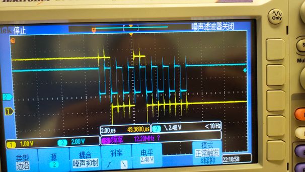
- When I configured SCLK_POL = 1 and SCLK_PHA = 1, SCLK_CTL = 0, DATA_CTL = 0, and I sent (0x90 0x00 0x00 0x00 0xff 0xff) to read W25Q128 ID, the oscilloscope waveform is like below(just show the sending data of 0x90. the blue is sclk and yellow is MOSI), the data(ID) read from W25Q128 is not correct, it is 0x0AD1:
- When I configured SCLK_POL = 1 and SCLK_PHA = 1, SCLK_CTL = 1, DATA_CTL = 0, and I sent (0x90 0x00 0x00 0x00 0xff 0xff) to read W25Q128 ID, the oscilloscope waveform is like below(just show the sending data of 0x90. the blue is sclk and yellow is MOSI), the data(ID) read from W25Q128 is not correct, it is 0x0000:
- When I tested on the STM32F407 board using the same SPI mode 3(SCLK_POL = 1 and SCLK_PHA = 1), the oscilloscope waveform is like below(just show the sending data of 0x90), and the data read from W25Q128 is correct, it is 0xef17:
As you can see, the waveform is different, and the STM32F407 wareform is the same with standard SPI mode 3.
So the question is why? And how can I set the correct SPI mode 3 of imx8mq?
I tried a lot, but all failed.
Hope you can help me.
Thanks.
Edward
- Mark as New
- Bookmark
- Subscribe
- Mute
- Subscribe to RSS Feed
- Permalink
- Report Inappropriate Content
Hi Edward
for i.MX8MQ ecspi mode configuration example one can look at MCUXpresso SDK_EVK-MIMX8MQ
available on https://mcuxpresso.nxp.com/en/welcome
..devices/MIMX8MQ6/drivers/fsl_ecspi.c function void ECSPI_SetChannelConfig(ECSPI_Type *base, ecspi_channel_source_t channel, const ecspi_channel_config_t *config)
For developing flash driver one can use as starting point example in ..driver_examples/ ecspi/ecspi_loopback/ecspi_loopback.c
Best regards
igor
- Mark as New
- Bookmark
- Subscribe
- Mute
- Subscribe to RSS Feed
- Permalink
- Report Inappropriate Content
Hi igorpadykov,
I just used the MCUXpresso SDK_EVK-MIMX8MQ v2.9.0 as you said. And I modified the driver example(loopback test) for my application. It did not work as I described in my post. I modified the modes by changing the channelConfig polarity, phase fields. Because it did not work, I changed the channelConfigclockInactiveState, dataLineInactiveState fields at the same time. It also did not work. Below is one of my setting.
===============================================================
masterConfig.channel = kECSPI_Channel0;
masterConfig.burstLength = 8;
masterConfig.samplePeriodClock = kECSPI_spiClock;
masterConfig.baudRate_Bps = 5000000;
masterConfig.chipSelectDelay = 0;
masterConfig.samplePeriod = 0;
masterConfig.txFifoThreshold = 1;
masterConfig.rxFifoThreshold = 0;
masterConfig.channelConfig.channelMode = kECSPI_Master;
masterConfig.channelConfig.clockInactiveState = kECSPI_ClockInactiveStateHigh;
masterConfig.channelConfig.dataLineInactiveState = kECSPI_DataLineInactiveStateLow;
masterConfig.channelConfig.chipSlectActiveState = kECSPI_ChipSelectActiveStateLow;
masterConfig.channelConfig.polarity = kECSPI_PolarityActiveLow;
masterConfig.channelConfig.phase = kECSPI_ClockPhaseSecondEdge;
ECSPI_MasterInit(pSpiInfo->baseAddr, &masterConfig, s_spiCb[id].srcclk);
===============================================================
Could you help me to test the driver for SPI mode 3 for real spi devices not loopback? I have already tried all the spi modes by configuring the ecspi register. And I found the ecspi controller always generates more half a cycle of the SCLK signal, which you can see from my previous post. I have no ideas. So I really really need your kindly help.
Best Regards,
Edward


