- Forums
- Product Forums
- General Purpose MicrocontrollersGeneral Purpose Microcontrollers
- i.MX Forumsi.MX Forums
- QorIQ Processing PlatformsQorIQ Processing Platforms
- Identification and SecurityIdentification and Security
- Power ManagementPower Management
- Wireless ConnectivityWireless Connectivity
- RFID / NFCRFID / NFC
- MCX Microcontrollers
- S32G
- S32K
- S32V
- MPC5xxx
- Other NXP Products
- S12 / MagniV Microcontrollers
- Powertrain and Electrification Analog Drivers
- Sensors
- Vybrid Processors
- Digital Signal Controllers
- 8-bit Microcontrollers
- ColdFire/68K Microcontrollers and Processors
- PowerQUICC Processors
- OSBDM and TBDML
- S32M
-
- Solution Forums
- Software Forums
- MCUXpresso Software and ToolsMCUXpresso Software and Tools
- CodeWarriorCodeWarrior
- MQX Software SolutionsMQX Software Solutions
- Model-Based Design Toolbox (MBDT)Model-Based Design Toolbox (MBDT)
- FreeMASTER
- eIQ Machine Learning Software
- Embedded Software and Tools Clinic
- S32 SDK
- S32 Design Studio
- GUI Guider
- Zephyr Project
- Voice Technology
- Application Software Packs
- Secure Provisioning SDK (SPSDK)
- Processor Expert Software
-
- Topics
- Mobile Robotics - Drones and RoversMobile Robotics - Drones and Rovers
- NXP Training ContentNXP Training Content
- University ProgramsUniversity Programs
- Rapid IoT
- NXP Designs
- SafeAssure-Community
- OSS Security & Maintenance
- Using Our Community
-
- Cloud Lab Forums
-
- Knowledge Bases
- ARM Microcontrollers
- i.MX Processors
- Identification and Security
- Model-Based Design Toolbox (MBDT)
- QorIQ Processing Platforms
- S32 Automotive Processing Platform
- Wireless Connectivity
- CodeWarrior
- MCUXpresso Suite of Software and Tools
- MQX Software Solutions
- RFID / NFC
-
- Home
- :
- Wireless Connectivity
- :
- Wireless Connectivity Knowledge Base
- :
- KW45/K32W1 32MHz & 32kHz Oscilllation margins
KW45/K32W1 32MHz & 32kHz Oscilllation margins
- Subscribe to RSS Feed
- Mark as New
- Mark as Read
- Bookmark
- Subscribe
- Printer Friendly Page
- Report Inappropriate Content
KW45/K32W1 32MHz & 32kHz Oscilllation margins
KW45/K32W1 32MHz & 32kHz Oscilllation margins
Generality on the Oscillation Margin
Outline
It is a margin to the oscillation stop and the most important item in the oscillation circuit.
This margin is indicated by ratio based on the resistance of crystal, and it shows how amplification oscillation capability the circuit has.
The oscillation circuit can theoretically operate if the oscillation margin is 1 or more. However, if oscillation margin is close to 1, the risk of operation failure will increase on module due to a too long oscillation start up time and so on. Such problems will be able to be solved by a larger oscillation margin.
It is recommended to keep 3 times or more as oscillation margin during the startup of the oscillation.
Factor of 10 is commonly requested for Automotive at startup and 5 for IoT market.
However, some providers accept to have 3 times as oscillation margin for steady state.
Here below is an oscillation example to explain better the phenomenon:
At start up, the configuration is set internally by the hardware in order to be sure to start the oscillation, the load capacitor is 0pF. After this time, it is the steady state and the load capacitor from the internal capabank is taken into account.
If load capacitor is not set correctly with the right oscillator gain, the oscillation will not be maintained after the start up.
The oscillator gain value will also depend on the resisting path on the crystal track.
A good way to evaluate it is to add a resistor on the crystal path and try to launch the oscillation.
In the SDK, the gain and the load capacitor can set directly in the application code.
Calculation
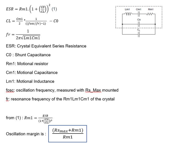
The oscillation margin is able to be calculated as follows:
The oscillation margin calculation is based on the motional resistor Rm by formula below :
Example: for the EVK board’s 32kHz crystal (NX2012SE)
ESR 80000,0 ohm
Rm1 79978,2 ohm
Lm1 3900 H
Cm1 6,00E-15 F
C0 1,70E-12 F
CL 1,25E-08 F
fr 32901,2 Hz
fosc 32771 Hz
Series Resistor Rsmax 7,50E+05 Ohm
Oscillation Margin 10,3
Measurement
- Requirements for measurement
- PCB
- Crystal unit (with equivalent circuit constants data)
- Resistors (SMD)
- Measurement equipment (Oscilloscope, Frequency counter or others capable to observe oscillation)
- Add a resistor to the resonator in serial and check if the oscillation circuit works or not.
- If the oscillation is confirmed by 2), change the resistor to larger. If there is no oscillation, change the resistor to smaller.
- Find out the maximum resistor (=Rs_max) which is the resistor just before the oscillation stop.
- Measure the oscillating frequency with Rs_max.
- Calculate the oscillation margin based on the Rs_max.
Notes
- The Oscillation margin is affected not only by crystal characteristics but also parts that compose the oscillation circuit (MCU, capacitor and resistor). Therefore, it is recommended to check the oscillation margin after the MCU functionality is checked on your module.
- The series resistor is only for the evaluation. Please do not use this resistor in actual usage.
- It is recommended to check the functionality of your module also. It is possible that the module does not work correctly due to a frequency shift on oscillation circuit and so on.
- Jig and socket could be used in measurement, but stray of them will give influence for oscillation margin.
KW45/K32W1 product oscillation margin overview
32MHz crystal
NXP recommends to use the quartz NDK NX1612SA (EXS00A-CS14160) or NDK NX2016SA (EXS00A-CS14161) to be compliant with the +/-50ppm required in Bluetooth LE.
Using the current SDK, NXP guarantees an oscillation margin of 10 for startup commonly used by Automotive customers and 3 for steady state.
Higher oscillation margin can be reached by using higher ISEL and CDAC parameters with some drawback respectively on the power consumption and the clock accuracy. ( the load capacitance bank (CDAC) and the oscillator amplifier current (ISEL))
NDK recommended / target values for oscillation margin is informed case by case.
On general basis requested oscillation margin has to be between recommended value and 3 times this value.
"NDK quartz provider (FR) explains this oscillation margin specification is only mandatory at the start-up phase, not at the steady state. Starting the oscillation is the phase that needs more energy. That's why the gain of the oscillator gain is at the maximum value which means not optimal consumption. When the oscillation stability is reached, the gain could be reduced to save power. The oscillation will not be affected.
Keep in mind a quartz oscillates by mechanical effect. So, when the oscillation is starting you need the highest energy to emulate it. By its own inertial, you need less energy to maintain the mechanical oscillation.
NDK provides a good picture of this. Starting up a crystal into oscillation is like a train what you would like to start moving. At the beginning the train is stopped and you need a lot of energy to start running. When the train is running at its nominal speed, you need less effort to maintain that movement and a very big effort to stop it completely."
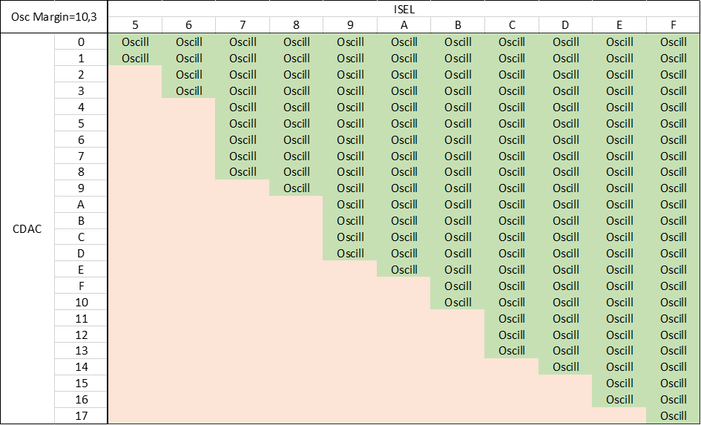
Example: for the oscillation margin 10 (Series Resistor Rsmax = 560W)
The CDAC/ISEL area where the oscillation starts and propagates in the internal blocks is defined (‘oscill’) in the table below.
32kHz crystal
NXP recommends to use the quartz NDK NX2012SE (EXS00A-MU01517) or NDK NX2012SA (EXS00A-MU00801) to be compliant with the +/-500ppm required in Bluetooth LE.
using the current SDK, the oscillation margin with this quartz is 10 with some limitation on the Crystal load capacitance selection (Cap_Sel) and the Oscillator coarse gain amplifier (ESR_Range) values, with some drawback respectively on the power consumption and the clock accuracy.
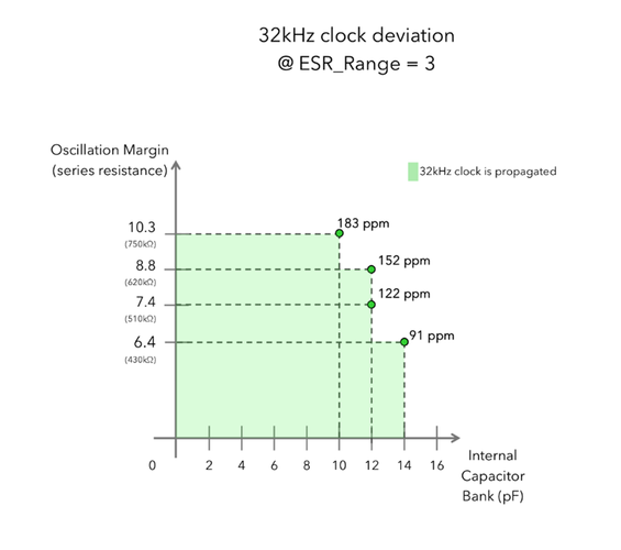
For an oscillation margin at 10 for instance, the Capacitor value from the databank (CapSel) is limited (green area) as shown in the graph below:
Example: for an oscillation margin at 6.4, if the load cap is set at 14pF and the ESR_Range to 3, the 32kHz frequency accuracy will be around 91ppm. From this point, the oscillation margin can be enlarged to 10.3 by decreasing the load cap to 10pF but the accuracy will be degraded (183ppm).
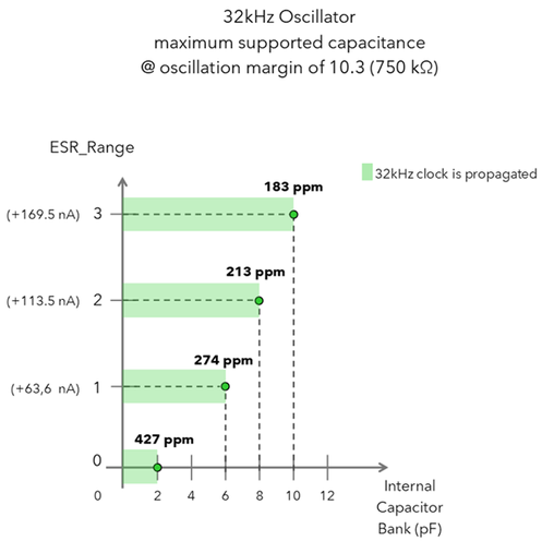
For an Oscillation margin at 10, the graph below is showing the ESR_Range versus the load cap. The possible load cap variation range (in green) is larger when the ESR_Range increases:
Example: at oscillation margin 10.3, the clock accuracy can be improved from 213ppm to 183ppm by setting the ESR_range 2 to an ESR_Range 3 but the current consumption will be increased to 169.5nA.
An other important point is that for a given ESR_Range value, getting higher the load cap is much more increasing the current than in the example above.
Remark: Under a high oscillation margin condition, the crystal voltage will be smaller.
Other possible ways to improve the oscillation margin exist:
- Use external capacitor instead of internal capacitor banks. Oscillation margin goes up to 10.
- Use the internal 32kFRO is supported for BLE (target:+/-500ppm)


