
- NXP Forums
- Product Forums
- General Purpose MicrocontrollersGeneral Purpose Microcontrollers
- i.MX Forumsi.MX Forums
- QorIQ Processing PlatformsQorIQ Processing Platforms
- Identification and SecurityIdentification and Security
- Power ManagementPower Management
- MCX Microcontrollers
- S32G
- S32K
- S32V
- MPC5xxx
- Other NXP Products
- Wireless Connectivity
- S12 / MagniV Microcontrollers
- Powertrain and Electrification Analog Drivers
- Sensors
- Vybrid Processors
- Digital Signal Controllers
- 8-bit Microcontrollers
- ColdFire/68K Microcontrollers and Processors
- PowerQUICC Processors
- OSBDM and TBDML
-
- Solution Forums
- Software Forums
- MCUXpresso Software and ToolsMCUXpresso Software and Tools
- CodeWarriorCodeWarrior
- MQX Software SolutionsMQX Software Solutions
- Model-Based Design Toolbox (MBDT)Model-Based Design Toolbox (MBDT)
- FreeMASTER
- eIQ Machine Learning Software
- Embedded Software and Tools Clinic
- S32 SDK
- S32 Design Studio
- Vigiles
- GUI Guider
- Zephyr Project
- Voice Technology
- Application Software Packs
- Secure Provisioning SDK (SPSDK)
- Processor Expert Software
-
- Topics
- Mobile Robotics - Drones and RoversMobile Robotics - Drones and Rovers
- NXP Training ContentNXP Training Content
- University ProgramsUniversity Programs
- Rapid IoT
- NXP Designs
- SafeAssure-Community
- OSS Security & Maintenance
- Using Our Community
-
- Cloud Lab Forums
-
- Home
- :
- Product Forums
- :
- S32K
- :
- SPI and I2C losing synchronization after reset
SPI and I2C losing synchronization after reset
- Subscribe to RSS Feed
- Mark Topic as New
- Mark Topic as Read
- Float this Topic for Current User
- Bookmark
- Subscribe
- Mute
- Printer Friendly Page
- Mark as New
- Bookmark
- Subscribe
- Mute
- Subscribe to RSS Feed
- Permalink
- Report Inappropriate Content
Hello everybody!
I am using a S32K144EVB to read some data from different sensors using both I2C and SPI communication protocols
The communication works fine until a press the reset button on the board or disconnect the board from the power supply. When the board is initialized, it loses the synchronization with the sensors and I am not able to read the data correctly anymore.
I have tried to program it using both the MBDT and the SDK, but I face the same problem in both environments.
May someone help me to understand what is going on, please?
I appreciate your assistance. Thank you!
Solved! Go to Solution.
- Mark as New
- Bookmark
- Subscribe
- Mute
- Subscribe to RSS Feed
- Permalink
- Report Inappropriate Content
I could solve the problem by powering the sensor using a GPIO pin. Thus, I just turn it off and on again before entering the main loop.
Thank you.
- Mark as New
- Bookmark
- Subscribe
- Mute
- Subscribe to RSS Feed
- Permalink
- Report Inappropriate Content
Hi,
do your MCU properly run the application from flash after reset/power on?
Do you see right signals on SPI and I2C buses that a connected sensor's protocol requires?
If MCU run as master, the MCU initiates and controls communication and sensor/slave should respond accordingly.
BR, Petr
- Mark as New
- Bookmark
- Subscribe
- Mute
- Subscribe to RSS Feed
- Permalink
- Report Inappropriate Content
Thank you for your reply, Petr.
The MCU properly runs the application after the reset because I can see the data in FreeMaster and the LED also changes accordingly to the read data.
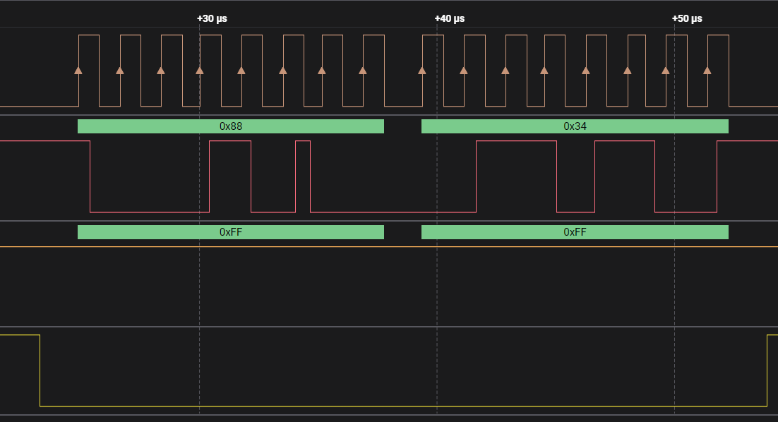
Using a data analyzer, I realized the data signals are shifted after the reset, so I usually miss a couple of bits, i.e. I have the same data being sent by the sensors, but they are not synchronized with the board anymore. Inserting a delay before initializing the pins and adding extra capacitors between the Vcc and GND helped, but didn't solve the problem completely.
The board runs as Master and I tried to add some delays (SCK to PCS, PCS to SCK and between transfers), but it also didn’t work.
- Mark as New
- Bookmark
- Subscribe
- Mute
- Subscribe to RSS Feed
- Permalink
- Report Inappropriate Content
The first picture shows the data as I am expecting, and the second data is what I get after pressing the "reset button". Basically, there is one bit missing, so all my data is shifted.
If I keep resetting it, I keep missing more bits.
My code is like this:
/* Including needed modules to compile this module/procedure */
#include "Cpu.h"
#include "clockMan1.h"
#include "pin_mux.h"
#include "Send.h"
#include "Receive.h"
#include "adConv1.h"
#include "PWM.h"
#include "osif1.h"
#include "dmaController1.h"
#if CPU_INIT_CONFIG
#include "Init_Config.h"
#endif
#define BUFFER_SIZE 2U
#define TIMEOUT 100U
volatile int exit_code = 0;
/* User includes (#include below this line is not maintained by Processor Expert) */
#include <stdint.h>
#include <stdbool.h>
//Received Data
uint8_t masterDataReceive[BUFFER_SIZE];
//Status of the SPI transfer
status_t sts;
// Delay function
void delay(volatile int cycles)
{
/* Delay function - do nothing for a number of cycles */
while(cycles--);
}
/*!
\brief The main function for the project.
\details The startup initialization sequence is the following:
* - __start (startup asm routine)
* - __init_hardware()
* - main()
* - PE_low_level_init()
* - Common_Init()
* - Peripherals_Init()
*/
int main(void)
{
/* Write your local variable definition here */
/*** Processor Expert internal initialization. DON'T REMOVE THIS CODE!!! ***/
#ifdef PEX_RTOS_INIT
PEX_RTOS_INIT(); /* Initialization of the selected RTOS. Macro is defined by the RTOS component. */
#endif
/*** End of Processor Expert internal initialization. ***/
ftm_state_t ftmStateStruct;
uint8_t masterDataSend[BUFFER_SIZE];
lpspi_state_t masterState;
/* Initialize pins
* - See PinSettings component for more info
*/
/* Initialize and configure clocks
* - see clock manager component for details
*/
CLOCK_SYS_Init(g_clockManConfigsArr, CLOCK_MANAGER_CONFIG_CNT,
g_clockManCallbacksArr, CLOCK_MANAGER_CALLBACK_CNT);
CLOCK_SYS_UpdateConfiguration(0U, CLOCK_MANAGER_POLICY_AGREEMENT);
PINS_DRV_Init(NUM_OF_CONFIGURED_PINS, g_pin_mux_InitConfigArr);
LPSPI_DRV_MasterDeinit(0U);
delay(5000000);
lpspi_master_config_t MasterConfigSPI = {
.bitsPerSec = 100000U,
.whichPcs = LPSPI_PCS0,
.pcsPolarity = LPSPI_ACTIVE_LOW,
.isPcsContinuous = true,
.bitcount = 8U,
.lpspiSrcClk = 8000000U, //48000000U,
.clkPhase = LPSPI_CLOCK_PHASE_1ST_EDGE,
.clkPolarity = LPSPI_SCK_ACTIVE_HIGH,
.lsbFirst = false,
.transferType = LPSPI_USING_INTERRUPTS,
};
/* Initialize LPSPI0 (Send)*/
LPSPI_DRV_MasterInit(0U, &masterState, &MasterConfigSPI);
LPSPI_DRV_MasterSetDelay(0U, 10U, 10U, 10U);
/* Variable used for the loop that initializes the data buffer */
uint16_t i;
// Data to be sent
for (i = 0u; i < BUFFER_SIZE; i++)
{
masterDataSend[i] = 255u;
}
while(1)
{
sts= LPSPI_DRV_MasterTransferBlocking(0U, &masterDataSend, &masterDataReceive, BUFFER_SIZE, TIMEOUT);
delay(50000);
}
/* Write your code here */
/* For example: for(;;) { } */
/*** Don't write any code pass this line, or it will be deleted during code generation. ***/
/*** RTOS startup code. Macro PEX_RTOS_START is defined by the RTOS component. DON'T MODIFY THIS CODE!!! ***/
#ifdef PEX_RTOS_START
PEX_RTOS_START(); /* Startup of the selected RTOS. Macro is defined by the RTOS component. */
#endif
/*** End of RTOS startup code. ***/
/*** Processor Expert end of main routine. DON'T MODIFY THIS CODE!!! ***/
for(;;) {
if(exit_code != 0) {
break;
}
}
return exit_code;
/*** Processor Expert end of main routine. DON'T WRITE CODE BELOW!!! ***/
} /*** End of main routine. DO NOT MODIFY THIS TEXT!!! ***/
/* END main */
/*!
** @}
*/
/*
** ###################################################################
**
** This file was created by Processor Expert 10.1 [05.21]
** for the Freescale S32K series of microcontrollers.
**
** ###################################################################
*/
- Mark as New
- Bookmark
- Subscribe
- Mute
- Subscribe to RSS Feed
- Permalink
- Report Inappropriate Content
I could solve the problem by powering the sensor using a GPIO pin. Thus, I just turn it off and on again before entering the main loop.
Thank you.