- NXP Forums
- Product Forums
- General Purpose MicrocontrollersGeneral Purpose Microcontrollers
- i.MX Forumsi.MX Forums
- QorIQ Processing PlatformsQorIQ Processing Platforms
- Identification and SecurityIdentification and Security
- Power ManagementPower Management
- MCX Microcontrollers
- S32G
- S32K
- S32V
- MPC5xxx
- Other NXP Products
- Wireless Connectivity
- S12 / MagniV Microcontrollers
- Powertrain and Electrification Analog Drivers
- Sensors
- Vybrid Processors
- Digital Signal Controllers
- 8-bit Microcontrollers
- ColdFire/68K Microcontrollers and Processors
- PowerQUICC Processors
- OSBDM and TBDML
-
- Solution Forums
- Software Forums
- MCUXpresso Software and ToolsMCUXpresso Software and Tools
- CodeWarriorCodeWarrior
- MQX Software SolutionsMQX Software Solutions
- Model-Based Design Toolbox (MBDT)Model-Based Design Toolbox (MBDT)
- FreeMASTER
- eIQ Machine Learning Software
- Embedded Software and Tools Clinic
- S32 SDK
- S32 Design Studio
- Vigiles
- GUI Guider
- Zephyr Project
- Voice Technology
- Application Software Packs
- Secure Provisioning SDK (SPSDK)
- Processor Expert Software
-
- Topics
- Mobile Robotics - Drones and RoversMobile Robotics - Drones and Rovers
- NXP Training ContentNXP Training Content
- University ProgramsUniversity Programs
- Rapid IoT
- NXP Designs
- SafeAssure-Community
- OSS Security & Maintenance
- Using Our Community
-
- Cloud Lab Forums
-
- Home
- :
- Product Forums
- :
- S12 / MagniV Microcontrollers
- :
- Buzzing noise on S12ZVM
Buzzing noise on S12ZVM
- Subscribe to RSS Feed
- Mark Topic as New
- Mark Topic as Read
- Float this Topic for Current User
- Bookmark
- Subscribe
- Mute
- Printer Friendly Page
Buzzing noise on S12ZVM
- Mark as New
- Bookmark
- Subscribe
- Mute
- Subscribe to RSS Feed
- Permalink
- Report Inappropriate Content
Hello,
We had a strange behaviour with the microcontroller MC9S12ZVMC128. When we power off/on several times, the motor randomly starts a buzzing noise. In this condition, it do nothing and have no communication. Other power off/on on actuator do not heal this behavior. The only way is to completely reflash the microcontroller with JTAG. The buzz comes from the oscillation of the coils at a frequency of around 200Hz.
I did a dump of the flash, eeprom and register for some buzzing motor and compare to a good one.
- The flash is clean. Nothing to report.
- The eeprom shows some differences, but doesn't seem to have any impact. It's possible that the power off/on occurs during an eeprom write.
- The registers show some differences. I will provide a table with the differences I got.
When I reflash a good or bad EEPROM (.Srec file from the dump of the EEPROM) without erasing memory sector before, I got also the buzzing effect. I have no buzzing when I reflash a good or bad eeprom with erasing sector before program and the motor works fine.
Do you have any idea where does it come from?
What hapen exactly when we reflash an .Srec file without erasing sector before?
Thank you for your help!
Best regards,
Bastien
- Mark as New
- Bookmark
- Subscribe
- Mute
- Subscribe to RSS Feed
- Permalink
- Report Inappropriate Content
Hello Bastien,
It depends on the algorithm that the programmer uses.
The EEPROM sectors must be erased before programming.
The Program EEPROM Command verifies the data though.
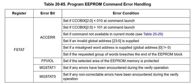
If there are ECC errors detected during the operation, MGSTATx bits are set, and the algorithm should handle that.
Anyway, you shold be able to read the EEPROM and compare it.
You mentioned that the MCU does nothing while it is under the conditions.
But in general, the MCU can be either in reset or do something.
If it not in reset, it is stuck somewhere.
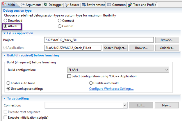
The debugger can be attached to the running MCU .
CW11:
Once attached, the debugger can halt the execution.
And you should see where it is stuck.
Best regards,
Daniel
- Mark as New
- Bookmark
- Subscribe
- Mute
- Subscribe to RSS Feed
- Permalink
- Report Inappropriate Content
Hello Daniel,
Thank you for your answer.
I check the FSTAT register and got this. When I'm connected, I do some play/pause and check the value in FSTAT.
- 0xEE (mostly)
- 0xA0 (rarely)
- 0x80 (rarely)
So it seem we have an Flash Access Error and an error is detected in MGSTAT. Not sure I interpret well the 0xEE, because in the datasheet, the value of bit 6 and 2 must be always 0.
I didn't know about the Attach function, that helps. Thanks for this.
I haven't figured out where it's stuck yet. I need more time to analyze the code further. For my initial observations, it seems to come back often on our eeprom read functions.
Best regards,
Bastien
- Mark as New
- Bookmark
- Subscribe
- Mute
- Subscribe to RSS Feed
- Permalink
- Report Inappropriate Content
Hi @BastienF,
The application SW should clear the ACCERR, FPVIOL flags before it launches any flash command whereas the MGSTAT flags are cleared automatically.
Do you clear the flags?
Most of the time, you should see FSTAT = 0x80.
The error flags should be read at the end of any flash operation when CCIF gets set to 1 again.
Please place a breakpoint at this condition.
Since MGSTAT0 = 1, I would say the application SW programs an EEPROM location that is not erased.
Regards,
Daniel
- Mark as New
- Bookmark
- Subscribe
- Mute
- Subscribe to RSS Feed
- Permalink
- Report Inappropriate Content
Hi Daniel,
Yes, it seem we clear the flags. I wanna double check with a colleague if we clear them in the good place.
The breakpoints doesn't work and I can't stop to check the correct value of register. So I investiguate by compilling differents SW with differents tests point to check on oscilloscope. It's took me time, but I found the function where it's stuck, I hope.
Since we have errror_u8 == ERR_OK (0), it should break the while, but doesn't seem to work.
Green: Test point DBG2
Blue: Test point DBG3
- Mark as New
- Bookmark
- Subscribe
- Mute
- Subscribe to RSS Feed
- Permalink
- Report Inappropriate Content
Hi @BastienF,
Maybe there is some kind of issue with the compiler's optimization.
Have you checked the disassembly?
If you can break it there, try placing an infinite loop there.
volatile unsigned int var = 1;
while(var){}
You should be able to halt the execution manually and find it there.
The debugger can clear the variable to proceed.
Regards,
Daniel
- Mark as New
- Bookmark
- Subscribe
- Mute
- Subscribe to RSS Feed
- Permalink
- Report Inappropriate Content
Hi Daniel,
We are not familiar with the disassembly, do you have some manual?
And do you think it's possible to get your help on site ?
We observe that breakpoints can be used at the very beginning of the SW. But we can't get them further into the SW, even though we can get test points out on the oscilloscope further down.
According to our latest investigations, it seems that this buzzing problem occurs when the power supply is cut off during an eeprom write. We're still investigating this last point.
Best regards,
Bastien
- Mark as New
- Bookmark
- Subscribe
- Mute
- Subscribe to RSS Feed
- Permalink
- Report Inappropriate Content
Hi @BastienF,
Regarding the assembler, have a look at S12Z CPU RM.
https://www.nxp.com/webapp/Download?colCode=S12ZCPURM
In the CW11 instalation directory, there are these documents:
MCU_S12Z_Compiler.pdf
MCU_S12Z_Assembler.pdf
Our team does not provide support at sites.
I see your company has a sale contact assigned.
We will send you an email.
The S12ZVM MCU has BATS module that monitors VSUP a gives a warning when VSUP drops below a certain level.
The EEPROM operation should be started only when there is no such warning.
The consumption of the MCU and the size of the bulk capacitor at VSUP should give you the expected time between the BATS warning and Low-voltage reset.
Regards,
Daniel
- Mark as New
- Bookmark
- Subscribe
- Mute
- Subscribe to RSS Feed
- Permalink
- Report Inappropriate Content
This is also functional safety related.
Please refer to the S12Z Safety Manual available in Secure files and an NDA.
Regadrs,
Daniel
- Mark as New
- Bookmark
- Subscribe
- Mute
- Subscribe to RSS Feed
- Permalink
- Report Inappropriate Content
And the data I get from the register. The test we done is a power on/off cycle of 4.2s during 5 days. During this 4.2s, our motor initialize and move a little bit. We have 4 motors for the data, PO1882, PO1883, PO1884 and PO1885. I extract the registers before to launch the test and after stoping the test. I hope it could help.
| Before test | Before test | Before test | Before test | After test | After test | After test | After test | |
| PO1882 | PO1883 | PO1884 | PO1885 | PO1882 buzzing | PO1883 no buzzing | PO1884 buzzing | PO1885 buzzing | |
| CPMUACLKTR | 0x04 | 0x08 | 0x08 | 0x10 | 0x04 | 0x00 | 0x08 | 0x10 |
| CPMUIRCTRIM | 0xB2DD | 0x9AB1 | 0x9AB1 | 0x92D2 | 0xB2DD | 0x0AA2 | 0x9AB1 | 0x92D2 |
| CAN0RXDLR | 0x3B | 0xB6 | 0xB6 | 0x65 | 0x3B | 0x1B | 0xB6 | 0xE5 |
| CAN0RXDSR0 | 0x06 | 0x37 | 0x37 | 0xB5 | 0x16 | 0x37 | 0x37 | 0xB5 |
| CAN0RXDSR1 | 0x59 | 0xB0 | 0xB0 | 0xA1 | 0x59 | 0xC0 | 0xB0 | 0xA1 |
| CAN0RXDSR2 | 0x88 | 0x35 | 0x35 | 0x66 | 0x88 | 0xA8 | 0x75 | 0x66 |
| CAN0RXDSR3 | 0x5C | 0xC0 | 0xC0 | 0xB2 | 0x5C | 0xDF | 0xE0 | 0xB2 |
| CAN0RXDSR4 | 0x40 | 0xD0 | 0xD0 | 0x1B | 0x60 | 0x08 | 0xD0 | 0x13 |
| CAN0RXDSR5 | 0x03 | 0x34 | 0x3C | 0x5F | 0x03 | 0x60 | 0x3C | 0x5F |
| CAN0RXDSR6 | 0x0D | 0xCA | 0xCA | 0x70 | 0x17 | 0x10 | 0xCA | 0x70 |
| CAN0RXDSR7 | 0xCC | 0xB3 | 0xB7 | 0x44 | 0x4C | 0x29 | 0xB7 | 0xC4 |
| CAN0RXIDR0 | 0x0C | 0x00 | 0x00 | 0x06 | 0x04 | 0x4E | 0x00 | 0x00 |
| CAN0RXIDR1 | 0x81 | 0x8F | 0x8E | 0x94 | 0x81 | 0x9A | 0x8F | 0x94 |
| CAN0RXIDR2 | 0x17 | 0x43 | 0x73 | 0x28 | 0x17 | 0x04 | 0x53 | 0x28 |
| CAN0RXIDR3 | 0x1C | 0x94 | 0x94 | 0xC1 | 0x14 | 0xD2 | 0x94 | 0xC0 |
| CAN0RXTSR | 0x4504 | 0x34DE | 0x34DE | 0x8AA0 | 0x6504 | 0x5198 | 0x34DE | 0x8AA0 |


