
- NXP Forums
- Product Forums
- General Purpose MicrocontrollersGeneral Purpose Microcontrollers
- i.MX Forumsi.MX Forums
- QorIQ Processing PlatformsQorIQ Processing Platforms
- Identification and SecurityIdentification and Security
- Power ManagementPower Management
- MCX Microcontrollers
- S32G
- S32K
- S32V
- MPC5xxx
- Other NXP Products
- Wireless Connectivity
- S12 / MagniV Microcontrollers
- Powertrain and Electrification Analog Drivers
- Sensors
- Vybrid Processors
- Digital Signal Controllers
- 8-bit Microcontrollers
- ColdFire/68K Microcontrollers and Processors
- PowerQUICC Processors
- OSBDM and TBDML
-
- Solution Forums
- Software Forums
- MCUXpresso Software and ToolsMCUXpresso Software and Tools
- CodeWarriorCodeWarrior
- MQX Software SolutionsMQX Software Solutions
- Model-Based Design Toolbox (MBDT)Model-Based Design Toolbox (MBDT)
- FreeMASTER
- eIQ Machine Learning Software
- Embedded Software and Tools Clinic
- S32 SDK
- S32 Design Studio
- Vigiles
- GUI Guider
- Zephyr Project
- Voice Technology
- Application Software Packs
- Secure Provisioning SDK (SPSDK)
- Processor Expert Software
-
- Topics
- Mobile Robotics - Drones and RoversMobile Robotics - Drones and Rovers
- NXP Training ContentNXP Training Content
- University ProgramsUniversity Programs
- Rapid IoT
- NXP Designs
- SafeAssure-Community
- OSS Security & Maintenance
- Using Our Community
-
- Cloud Lab Forums
-
- Home
- :
- Software Forums
- :
- Processor Expert Software
- :
- question
question
- Subscribe to RSS Feed
- Mark Topic as New
- Mark Topic as Read
- Float this Topic for Current User
- Bookmark
- Subscribe
- Mute
- Printer Friendly Page
- Mark as New
- Bookmark
- Subscribe
- Mute
- Subscribe to RSS Feed
- Permalink
- Report Inappropriate Content
Hello,
I use KE02Z familiy (MKE02Z64VLH2) microcontroller and I will use Interrupts with Processor Expert.
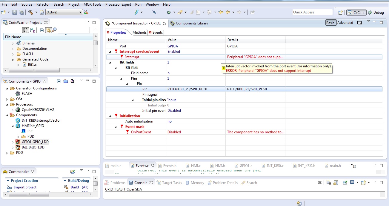
I add KBI1/KBI0 component for specfic pin to my project but when I want to configure it as a enable interrupt, I will get the message "ERROR: Peripheral "GPIO" does not support interrupt".
Why?
Please check the attachments.
Thank you,
Siamack
Solved! Go to Solution.
- Mark as New
- Bookmark
- Subscribe
- Mute
- Subscribe to RSS Feed
- Permalink
- Report Inappropriate Content
Hi Siamack,
Which IDE are you using? CW10.6 or KDS?
I created a project in KDS_3.0 + PE (Processor Expert) for the MKE02Z64VQH4 that is present on the Freedom FRDM-KE02Z4 board.
I used PE to pull in Keyboard and GPIO Components.
I only enabled the KBI0 pin 0 (PTA0) that goes to J2 pin 2 so that I could use a wire tied to ground to act as a switch. I had to enable a internal pull-up resistor too.
When you run the application, the Blue LED comes on, touch and PTA4 with the ground wire will cause KBI0 isr (I places the code in Events.c). The ISR clears the KBI0 interrupt and toggles the Blue LED. Repeated touch of the PTA4 pin and release will toggle the Blue LED.
Hope this helps.
Note I wasn't setting up interrupts for the GPIO. I set it up for the KBI0.
Regards,
David
- Mark as New
- Bookmark
- Subscribe
- Mute
- Subscribe to RSS Feed
- Permalink
- Report Inappropriate Content
Hello David,
Thank you for your useful answer. I use Codewarrior 10.6 with Freedom FRDM-KE02Z4 board and MKE02Z64VQH2 CPU on board.
Now I have found the Init_KBI component in PE, and I added this component to my project.
I write the name of ISR in configuration of the component as you did, and then PE generated a method in KBI0.h as your example as your example: PE_ISR(my_kbio0_int)
Now I want to add several pins and every pin is connected to own key, so I need separate interrupt for each pin, how should I implement it?
In other words, if I want to for example pin PTA0 light the blue LED and PTA1 increment a counter, how can I implement this two in "Events" independently?
Is it possible you extend your example i.e. for two independent pins?
Thank you!
Kind regards,
Siamack
- Mark as New
- Bookmark
- Subscribe
- Mute
- Subscribe to RSS Feed
- Permalink
- Report Inappropriate Content
Hi Siamack,
I am on PTO today so sorry for short reply.
The KE02 KBI only has one interrupt source.
Therefore in the ISR you have to read the KBIx_SP register to see which key/pin caused the interrupt and then have code to do whatever you want for the response.
Regards,
David
- Mark as New
- Bookmark
- Subscribe
- Mute
- Subscribe to RSS Feed
- Permalink
- Report Inappropriate Content
Hi David,
Thank you for replay.
Right, but I could not find the KBIx_SP register and I need an example which shows how to read which key/pin caused the interrupt.
If it's possible for you during the week send me an example, I will be very thankful!
Kind regards,
Siamack Ghadimi
- Mark as New
- Bookmark
- Subscribe
- Mute
- Subscribe to RSS Feed
- Permalink
- Report Inappropriate Content
Hi Siamack,
My apologizes. The KBIx_SP is in the KE06 and not KE02.
For the KE02 you need to look at the GPIOx_DIR register and its associated bit field to determine which key/pin/bit is pressed/asserted.
PE does create the KBI ISR for you in the respective KBIn.c Generated source file but the note indicates you need to copy it and place it in your own code or the Events.c. I choose the Event.c to copy it to and then add code inside the ISR.
Attached is my updated project. You just need to add more pins and check for them in the ISR.
NOTE: I am not doing any debouncing or filtering of the input. So depending on your keyboard input you may need to debounce.
Regards,
David
- Mark as New
- Bookmark
- Subscribe
- Mute
- Subscribe to RSS Feed
- Permalink
- Report Inappropriate Content
Hi David,
Thank you very much, after few changed in your example, my code now works :smileyhappy:
Have few questions:
1- I did not used pull-up resistor, is have any impackt?
2- Why we should clear KBI0 interrupts everytime?
3- Do you have any example regarding debouncing?
Again many thanks for your help!!!
Kind regards,
Siamack
- Mark as New
- Bookmark
- Subscribe
- Mute
- Subscribe to RSS Feed
- Permalink
- Report Inappropriate Content
Hi Siamack,
Glad you have it working.
A1) is the pin is little load then you can use the internal pull-up resistor. If pin has much loading, then an external resistor is required. Each hardware environment is different.
A2) Generically speaking I setup the ISR for reacting to one keyboard input so the code clears the interrupt. But if multiple keys are pressed, your code needs to scan through all the potential key's to see if more than one key is pressed and decide if you want to handle all keys in the isr in one pass or setup isr to handle one at a time and only clear isr when no keys are pressed. Again it is system dependent.
A3) No. But the KE02 does have a PORT_IOFLT register that can setup a glitch filter for the KBI0 and KBI1 that can act as a debouncing mechanism. Should it not be able to work completely in your environment then you might need low pass filter on the pins.
Regards,
David
- Mark as New
- Bookmark
- Subscribe
- Mute
- Subscribe to RSS Feed
- Permalink
- Report Inappropriate Content
Hi David,
Thank you!
I make my qestion short:
I use 8 keys and in my code I have prioritized each pins. So if two or more keys press the program choose higher priority key.
But I have a case which when two specific keys pressed the program should handle it in different way.
Now as I understand in any case the GPIO register will register one or more key press before it cleared? Am I in right approach?
By the way do you have any example code for how to set up PORT_IOFLT?
Again many thanks.
Kind regards,
Siamack
- Mark as New
- Bookmark
- Subscribe
- Mute
- Subscribe to RSS Feed
- Permalink
- Report Inappropriate Content
Hi Siamack,
Please add a Init_PORT Component to your project.
In the Component Inspector go to All->Settings->Filters.
For "Filter division" change the Set 3 from LPOCLK to LPOCLK/128.
For "Filter selection" both KBI0 and KBI1 to "FLTDIV3".
Re-generte code, compile and run.
The Glitch Filter is set for maximum delay. You can play with the settings to reduce the time and improve responsiveness to meet your hardware needs.
Regards,
David
- Mark as New
- Bookmark
- Subscribe
- Mute
- Subscribe to RSS Feed
- Permalink
- Report Inappropriate Content
Hi David,
Still I did not get time to test it but soon I will do it, anyhow thank you!
Regards,
Siamack