- NXP Forums
- Product Forums
- General Purpose MicrocontrollersGeneral Purpose Microcontrollers
- i.MX Forumsi.MX Forums
- QorIQ Processing PlatformsQorIQ Processing Platforms
- Identification and SecurityIdentification and Security
- Power ManagementPower Management
- MCX Microcontrollers
- S32G
- S32K
- S32V
- MPC5xxx
- Other NXP Products
- Wireless Connectivity
- S12 / MagniV Microcontrollers
- Powertrain and Electrification Analog Drivers
- Sensors
- Vybrid Processors
- Digital Signal Controllers
- 8-bit Microcontrollers
- ColdFire/68K Microcontrollers and Processors
- PowerQUICC Processors
- OSBDM and TBDML
-
- Solution Forums
- Software Forums
- MCUXpresso Software and ToolsMCUXpresso Software and Tools
- CodeWarriorCodeWarrior
- MQX Software SolutionsMQX Software Solutions
- Model-Based Design Toolbox (MBDT)Model-Based Design Toolbox (MBDT)
- FreeMASTER
- eIQ Machine Learning Software
- Embedded Software and Tools Clinic
- S32 SDK
- S32 Design Studio
- Vigiles
- GUI Guider
- Zephyr Project
- Voice Technology
- Application Software Packs
- Secure Provisioning SDK (SPSDK)
- Processor Expert Software
-
- Topics
- Mobile Robotics - Drones and RoversMobile Robotics - Drones and Rovers
- NXP Training ContentNXP Training Content
- University ProgramsUniversity Programs
- Rapid IoT
- NXP Designs
- SafeAssure-Community
- OSS Security & Maintenance
- Using Our Community
-
- Cloud Lab Forums
-
- Home
- :
- Product Forums
- :
- Other NXP Products
- :
- FS23 does not enter in debug mode
FS23 does not enter in debug mode
- Subscribe to RSS Feed
- Mark Topic as New
- Mark Topic as Read
- Float this Topic for Current User
- Bookmark
- Subscribe
- Mute
- Printer Friendly Page
FS23 does not enter in debug mode
- Mark as New
- Bookmark
- Subscribe
- Mute
- Subscribe to RSS Feed
- Permalink
- Report Inappropriate Content
Hi everyone, I'm having issues in detecting the debug mode using an SBC FS23 in pair with a S32K312 microcontroller.
More specifically I'm using an SBC FS23 with HVBUCK regulator.
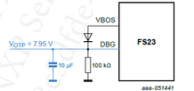
As suggested by SBC datasheet, I connected DBG pin to VBOS output (using a diode in series between the two pins); then I use the Sbc_fs23 APIs in order to initialize the SBC and configuring RSTb impact on watchdog refresh; code runs well, but when I use the debugger to break the execution of the code when watchdog total timeout expires SBC goes into fail state, resetting microcontroller and power line (100ms).
Reading the M_SYS1_CFG register (address 0x06), the reported value is 0x0100, so the DBG_MODE is set to 0 and thus the device is not in debug mode.
I checked voltage levels at pin VBOS, VDBG and VDIG and they seems to be within the expected range for the device to enter in debug mode. Also, the OTP programming load should not be bypassed (M_SYS1_CFG bit LOAD_OTP_BYP set to 0); the only value in M_SYS1_CFG set to one is VBOS2V1_SW_ALWAYS_EN.
From my understanding of datasheet, with a new cold start the debug mode shall be detected in this way, but, it does not happen; I also tried to open the circuit and force +5V on the DBG pin but the device seems not to go in debug mode.
Do you have any suggesetion? Thanks in advance
- Mark as New
- Bookmark
- Subscribe
- Mute
- Subscribe to RSS Feed
- Permalink
- Report Inappropriate Content
Hi David, sorry for the delay in the response.
The circuitry is similar to the one present in datasheet which is the same that you posted, with the only exception of the 10 uF capacitor and a jumper between the DBG pin and the diode cathode.
We tried both to apply +12 V at the DBG pin both with Power Supply direct connection and by passing PS ramp up time by plugging in power connector with power supply output already at steady states, the timing of the voltage changed but we could not see any differences in the behavior described (SBC register show DBG_MODE =0). Also, we tried to directly apply that voltage on DBG pin with another Power supply, same results.

Regarding the voltages sequence, with the proposed circuitry is not possible to have Vdbg > Vsup before Vsup gets high, since the Vbos output depends on Vsup. In any case, the circuit should be working if all the transitions are within a brief time interval.
May be something sw related? I am using the Sbc_fs23 library v 0.9.0, if I perform a refresh of the watchdog after the init function and then I try to breake the code for debugging the device seems not to recognise that dbg mode; if I do not do any further refresh after the one performed in library init function, then I can break the code and debugging, but in any case the DBG_MODE register bit remains set to 0.
BR
- Mark as New
- Bookmark
- Subscribe
- Mute
- Subscribe to RSS Feed
- Permalink
- Report Inappropriate Content
Hello cf_st,
I am pleased to contact you again.
Please note that the voltage to apply at the DBG pin to enter in Debug mode is 4.5V. Could you please try with such voltage level and then read the M_SYS1_CFG register?
As we know, the FS23 enters Debug mode in M3 state of the main state machine when VDBG (DBG pin voltage) > VDBG_MODE. NXP recommends connecting the DBG pin to the VBOS pin through a diode (VDBG = VBOS – Vd ≈ 4.1 V).
Regards,
David
- Mark as New
- Bookmark
- Subscribe
- Mute
- Subscribe to RSS Feed
- Permalink
- Report Inappropriate Content
Hello,
I hope all is great with you. Thank you for using the NXP communities.
Could you please share the voltage at the VDBG pin? It is greater than VDBG_MODE?
Are you following the sequence below?
Is your Debug pin (DBG) circuitry as follows?
I hope this information helps.
Regards,
David


