
- NXP Forums
- Product Forums
- General Purpose MicrocontrollersGeneral Purpose Microcontrollers
- i.MX Forumsi.MX Forums
- QorIQ Processing PlatformsQorIQ Processing Platforms
- Identification and SecurityIdentification and Security
- Power ManagementPower Management
- MCX Microcontrollers
- S32G
- S32K
- S32V
- MPC5xxx
- Other NXP Products
- Wireless Connectivity
- S12 / MagniV Microcontrollers
- Powertrain and Electrification Analog Drivers
- Sensors
- Vybrid Processors
- Digital Signal Controllers
- 8-bit Microcontrollers
- ColdFire/68K Microcontrollers and Processors
- PowerQUICC Processors
- OSBDM and TBDML
-
- Solution Forums
- Software Forums
- MCUXpresso Software and ToolsMCUXpresso Software and Tools
- CodeWarriorCodeWarrior
- MQX Software SolutionsMQX Software Solutions
- Model-Based Design Toolbox (MBDT)Model-Based Design Toolbox (MBDT)
- FreeMASTER
- eIQ Machine Learning Software
- Embedded Software and Tools Clinic
- S32 SDK
- S32 Design Studio
- GUI Guider
- Zephyr Project
- Voice Technology
- Application Software Packs
- Secure Provisioning SDK (SPSDK)
- Processor Expert Software
-
- Topics
- Mobile Robotics - Drones and RoversMobile Robotics - Drones and Rovers
- NXP Training ContentNXP Training Content
- University ProgramsUniversity Programs
- Rapid IoT
- NXP Designs
- SafeAssure-Community
- OSS Security & Maintenance
- Using Our Community
-
- Cloud Lab Forums
-
- Home
- :
- Model-Based Design Toolbox (MBDT)
- :
- Model-Based Design Toolbox (MBDT)
- :
- Re: TJA1153- How to use TJA1153_Init(mbdt_tja1153.h)
TJA1153- How to use TJA1153_Init(mbdt_tja1153.h)
- Subscribe to RSS Feed
- Mark Topic as New
- Mark Topic as Read
- Float this Topic for Current User
- Bookmark
- Subscribe
- Mute
- Printer Friendly Page
TJA1153- How to use TJA1153_Init(mbdt_tja1153.h)
- Mark as New
- Bookmark
- Subscribe
- Mute
- Subscribe to RSS Feed
- Permalink
- Report Inappropriate Content
We are trying to enable CAN4,CAN5 on MR-CANHUBK344 which has TJA1153.
Currently, I am creating it based on the following sample code, but it is not working.
sample:S32K3_Examples\can\s32k344_can_fd_receive_ebt
The following items are set, but are there any other items that need to be set?
(CAN0~3, which is not the other TJA1153, is active)
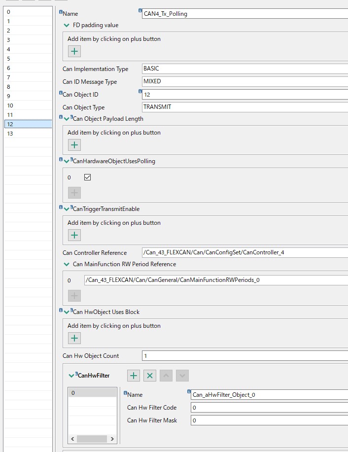
1. canExtHwID (Can Object ID that CAN4,CAN5 polling TRANSMIT Config )
2. Output ch Config(EN,Stb),
3. Input ch Config (Errn)
4. CAN4,5 polling TRANSMIT config
NXP_MBDToolbox_S32K3xx ver1.4.0
NXP_Support_Package_S32K3xx ver 1.4.0

Regards,
- Mark as New
- Bookmark
- Subscribe
- Mute
- Subscribe to RSS Feed
- Permalink
- Report Inappropriate Content
Hello @po1 ,
I looked over the attached configuration file and everything seemed to be in order regarding the CAN peripheral settings and the associated pins.
From your reply I understand that you managed to communicate using the CAN instances CAN0, CAN1, CAN2 and CAN3 and that the problem only happens with CAN4 and CAN5.
I have one possible solution for the problem, and that involves disconnecting the power supply from the board completely and then connecting it again. Power cycling the board makes sure that the transceiver is ready for initialization.
Note: for this solution, pressing the reset button is not sufficient.
Please let us know if the CAN4 and CAN5 instances are working properly after the power cycle.
Alternatively, if it still does not work, could you please provide a picture of the hardware setup?
Regards,
Robert V
- Mark as New
- Bookmark
- Subscribe
- Mute
- Subscribe to RSS Feed
- Permalink
- Report Inappropriate Content
Thanks for your support and useful information.
We confirmed the following items from the information we received.
1. I checked the hardware parts and made sure they were set to S32K344-Q172.
2. For pins, peripherals, clocks and interrupts, I checked them correct from the tutorial you gave me and MR-CANHUBK344-SCH.pdf.
We also confirmed that it is fine to set the LED from inputs such as Use_SW1 or 2.
3. How to check CAN transmission and reception of CAN channels 0~3.
• Transmission: Confirmed with CANalyzer connected to VN1610.
・ Reception: Confirmed with the internal RAM value using FreeMASTER.
We've reviewed the above, but we haven't resolved the issue yet.
Currently, it is set in the attached file.
Could you continue to give us some advice on what other points we should check?
Regards,
- Mark as New
- Bookmark
- Subscribe
- Mute
- Subscribe to RSS Feed
- Permalink
- Report Inappropriate Content
Hi @po1
The attached screenshots addressing the transceiver initialization in your model, and the configuration of the polling objects used for this process seem to be correct, however, there could be multiple causes for your model not displaying the expected behavior when deployed on the MR-CANHUBK344 evaluation board.
For being able to provide a complete solution to your issue, could you please help us with some details on the following items?
1. The CAN examples delivered with the MBDT for S32K3 are set to target an S32K344-Q257 processor, while the MR-CANHUBK344 is based on S32K344-Q172. Are your model, and its associated .mex file, that you have updated with CAN4 and CAN5 configurations, set for S32K344-Q172? If not, for a correct application behavior, I would recommend you to configure your Simulink model for the S32K344-Q172 Hardware Part, by opening the Model Settings, going to Target Hardware Resources -> Hardware -> Hardware Part dropdown, as illustrated below. After doing this please make sure you press the Apply button.

Also, please note that this process will replace the configuration associated to your model with the default one we provide for S32K344-Q172 processor. So, please consider backing up the .mex file that you have already modified before this process. After that, you could enable the CAN4 and CAN5 instances inside the new configuration, targeting S32K344-Q172, by pressing the Configure button of any of the MBDT blocks.
1. For a complete guide on how to enable CAN on MR-CANHUBK344, could you please check the following article (link)? It is addressing all the steps that need to be performed in terms of the hardware configuration - Pins, Peripherals, Clocks and Interrupts.
2. For the s32k344_can_fd_receive_ebt application, could you please let us know how are you testing that the messages are correctly received by the board? If the LED is not toggling at each received message, as described in the model's readme file, the problem could be related to the configuration of the LEDs inside the .mex file. The default S32K344 configuration projects MBDT delivers were developed for a different evaluation board, so the RGBLED0_BLUE (toggled inside the CanIf_RxIndication callback) configuration may not correspond to one of the LEDs on MR-CANHUBK344. For more details on how to configure the LEDs on MR-CANHUBK344, I would like to recommend to you this article (link), describing in a detailed manner all the steps that need to be performed.
3. As an additional recommendation, I would propose to you to also try running the s32k344_can_fd_send_ebt example. You can connect a CAN Analyzer to the board and set it up with the settings corresponding to your configuration. In this way we could check if the board successfully transmits messages on the CAN bus, thus validating the hardware configuration of the peripheral.
Please let us know if these inputs help you with the issue that you are currently encountering. If you are facing any other problems, please let us know so that we could perform further investigations.
Thank you,
Irina