
- NXP Forums
- Product Forums
- General Purpose MicrocontrollersGeneral Purpose Microcontrollers
- i.MX Forumsi.MX Forums
- QorIQ Processing PlatformsQorIQ Processing Platforms
- Identification and SecurityIdentification and Security
- Power ManagementPower Management
- MCX Microcontrollers
- S32G
- S32K
- S32V
- MPC5xxx
- Other NXP Products
- Wireless Connectivity
- S12 / MagniV Microcontrollers
- Powertrain and Electrification Analog Drivers
- Sensors
- Vybrid Processors
- Digital Signal Controllers
- 8-bit Microcontrollers
- ColdFire/68K Microcontrollers and Processors
- PowerQUICC Processors
- OSBDM and TBDML
-
- Solution Forums
- Software Forums
- MCUXpresso Software and ToolsMCUXpresso Software and Tools
- CodeWarriorCodeWarrior
- MQX Software SolutionsMQX Software Solutions
- Model-Based Design Toolbox (MBDT)Model-Based Design Toolbox (MBDT)
- FreeMASTER
- eIQ Machine Learning Software
- Embedded Software and Tools Clinic
- S32 SDK
- S32 Design Studio
- GUI Guider
- Zephyr Project
- Voice Technology
- Application Software Packs
- Secure Provisioning SDK (SPSDK)
- Processor Expert Software
-
- Topics
- Mobile Robotics - Drones and RoversMobile Robotics - Drones and Rovers
- NXP Training ContentNXP Training Content
- University ProgramsUniversity Programs
- Rapid IoT
- NXP Designs
- SafeAssure-Community
- OSS Security & Maintenance
- Using Our Community
-
- Cloud Lab Forums
-
- Home
- :
- Product Forums
- :
- ColdFire/68K Microcontrollers and Processors
- :
- 54417 "split" FlexBus chip select
54417 "split" FlexBus chip select
- Subscribe to RSS Feed
- Mark Topic as New
- Mark Topic as Read
- Float this Topic for Current User
- Bookmark
- Subscribe
- Mute
- Printer Friendly Page
- Mark as New
- Bookmark
- Subscribe
- Mute
- Subscribe to RSS Feed
- Permalink
- Report Inappropriate Content
Hi,
We're developing with a NetBurner MOD54417, using the CS5 chip select and the FlexBus in 8 bit (no burst) mode. The peripheral
will be FTDI's FT232H USB chip in asynchronous FIFO mode. I'm new to the ColdFire, but I think I have it set properly for the bus
mode we want. However, CS5 is asserting twice during a byte write - once in the address setup cycle and once for the data. The
FlexBus specs show it as a single assertion. I'm thinking I must be missing something outside of the usual csar, csmr, and cscr
register setup. I realize I'll have to manipulate the timing a bit with a latch or counter to get the FT232H timing right, but I don't want
to deal with a doubled up chip select assertion as part of that.
NetBurner doesn't meddle with the CS5 signal from the ColdFire, they only have an address latch on board to de-multiplex the bus.
Register values for CS5:
csar = 0x04000000
cscr = 0x1140; //no CS5 delay, 4 waits (38 ns. CS assertion width)
csmr = 0x00000001
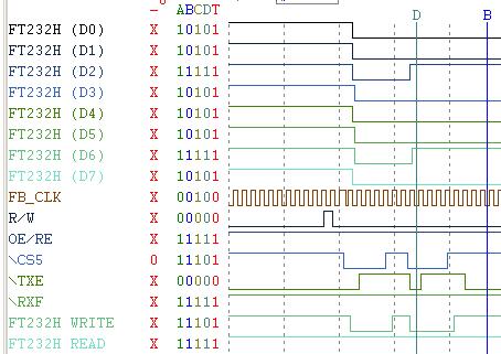
Attached is the logic analyzer trace. Cursor D is just to the right of the data becoming valid.
Any feedback on this issue will be greatly appreciated!
Regards,
Ray
Solved! Go to Solution.
- Mark as New
- Bookmark
- Subscribe
- Mute
- Subscribe to RSS Feed
- Permalink
- Report Inappropriate Content
I made a lot of wrong assumptions in my code, but I did get one thing right. I typed:
> So I can see two separate write cycles to two different addresses.
>
>If you think your code is meant to be performing only a single write, then maybe the code
> is performing a WORD (16-bit) write which the FlexBus controller will convert to two successive writes.
Your code is:
> *(unsigned short *)(PC_SIDE_B_IO) = (unsigned char)'?'; //Write char to PC
Change that to "*(unsigned char *)(PC_SIDE_B_IO) = ..." and it will work as expected.
This was obviously what was happening, given that I was reading the CPU manual.
http://cache.freescale.com/files/32bit/doc/ref_manual/MCF54418RM.pdf?fpsp=1

Maybe you lifted your code from this or a similar Netburner App Note:
http://www.netburner.com/mod54415/application-notes-3/48-i2c-io-expansion-5/file
Their code configured the port as being 16 bits wide and uses "*(unsigned short *)". That would have worked for you.
There's something very strange with the Netburner sample code in the above App Note though. Either it is wrong or their structure definitions delcare the CSAR registers as the upper 16 bits only:
//Enable the Write Chip Select
sim.cs[1].cscr = 0x2180; // 0010 0001 1000 0000
sim.cs[1].csmr = 0x00000001;
sim.cs[1].csar = ( IO_DIG_WR >> 16 );
The CPU CSAR register is 32 bits with the lower 16 unused. The above code is shifting the address into those UNUSED bits or (more likely) it has declared that register as being 16 bits only. Which wouldn't matter except it doesn't match your code. But yours is working, so they must be using different definitions in the library you use and the one used for the app note. Beware.
Tom
- Mark as New
- Bookmark
- Subscribe
- Mute
- Subscribe to RSS Feed
- Permalink
- Report Inappropriate Content
> NetBurner MOD54417, using the CS5 chip select and the FlexBus in 8 bit (no burst) mode. The peripheral will be FTDI's FT232H USB chip
The MCF54417 has two USB ports on it already. You seem to be adding a third. Are there pin or package conflicts, or is the FTDI chip easier to get software for?
Tom
- Mark as New
- Bookmark
- Subscribe
- Mute
- Subscribe to RSS Feed
- Permalink
- Report Inappropriate Content
We have a few good reasons to add our own USB, Tom.
1) NetBurner only brings out one USB port from their module, we need two.
2) NetBurner has no USB support in their APIs (yet), and I don't want to go there myself.
3) Our Rabbit 3000 product (being replaced by the ColdFire product) used FTDI's FT232R chips (UART to USB) and the FTDI driver and our code in our connected Windows software works great and we don't want to reinvent that. It's very simple to modify that code to work with the FT232H in async FIFO mode, but we get serious speed advantages with the bus vs. UART strategy.
Regards,
Ray
- Mark as New
- Bookmark
- Subscribe
- Mute
- Subscribe to RSS Feed
- Permalink
- Report Inappropriate Content
Thanks for providing the logic trace. It looks pretty clear what is happening.
> CS5 is asserting twice during a byte write - once in the address setup cycle and once for the data.
Your trace doesn't show FB_ALE so you don't actually know when the address part of the cycle is.
What I can see is CS being asserted for about 5 clocks. Since you have Internal Termination programmed, FB_CSn should be asserted for ONE clock plus the number of wait states. In your case that is set to 4 so EACH of those 5-clock FB_CS5 assertions is one whole and separate bus cycle.
So I can see two separate write cycles to two different addresses.
If you think your code is meant to be performing only a single write, then maybe the code is performing a WORD (16-bit) write which the FlexBus controller will convert to two successive writes. That probably isn't what is happening as the addresses aren't sequential.
If you look at the Data Bus you can see the first cycle has 0x00 on the data bus and the second has 0x41.
Which pins on the CPU do you have "FT232H (D0-7)" connected to?
I'm guessing you may have them connected to FB_AD[7:0] given the signals I see on them.
If I'm right, since it is a multiplexed address and data bus, the first cycle is a write (as R/W is low) to the address 0x??????00 and the second one is to 0x??????41.
The value on those pins doesn't change between the address and the data parts of the cycle as the CPU doesn't change FB_AD[23] during byte cycles. Look at "Figure 20-14. Single Word-Write Transfer" in the Reference Manual.
The Data for a byte write is written and read on FB_AD[31:24].
If you do have the wiring correct, and have the FT232 connected to the UPPER 8 bits of the Flexbus, then your code is writing 0x00 to 0x00?????? followed by a write of 0x41 to 0x41000000.
Since CSAR is set to 0x04000000 that is impossible. You can only see addresses from 0x0400000000 to 0x04FFFFFFFF on the bus.
So I think you're using the wrong end of the Flexbus.
Welcome to the world of BIG_ENDIAN CPUs. The MSB one at the left is "Byte 0" and the LSB one on the right is "Byte 3".
If you do have made the boards with the FT232H connected to FB_AD[7:0] and need to leave it like that, or just want to test it, change the port to be 32-bit and then address the chip with sequential 32-bit addresses with the data in the lowest 8 bits.
Tom
- Mark as New
- Bookmark
- Subscribe
- Mute
- Subscribe to RSS Feed
- Permalink
- Report Inappropriate Content
Thank you for taking a look at this, Tom. The FT232H is in fact attached to the high byte of the bus. I label them D0 - D7 for convenience from a peripheral viewpoint. The NetBurner MOD54415 and MOD54417 modules only bring out the 2 high bytes to developers. Also, they don't bring out the ALE signal, but they do latch the address on their module. The logic traces show "D0 - D7" as all "0" during the first CS5 assertion; this would be the low byte of the address from the on-module latch. I didn't probe the high byte (AD8 - AD15) with the logic analyzer as there are enough probes hanging off the test rig as is.
The 2nd CS5 assertion is in fact my data. In this case (and the trace I posted earlier), just the letter "D" (ASCII 01000100) being sent. I've included the state list view for cursor B, at 1,452 ns. showing the "D" in Group 1:

If I change my code to output the letter "S" instead, I get the following trace, with an "S" (ASCII 01010011) at 1,372 ns. in the state list (cursor B):

I can do this all day long with anything that fits in a char. Here's my code - I'm using the NetBurner libraries:
//Side A not used in test rig yet
#define PC_SIDE_A_IO 0x02000000
#define PC_SIDE_B_IO 0x04000000
#define PC_SIDE_B_TX J2[36]
#define PC_SIDE_B_RX J2[15]
extern "C" {
void UserMain(void * pd);
}
const char * AppName="DynaCore";
void UserMain(void * pd) {
InitializeStack();
if (EthernetIP == 0) GetDHCPAddress();
OSChangePrio(MAIN_PRIO);
EnableAutoUpdate();
EnableTaskMonitor();
#ifndef _DEBUG
EnableSmartTraps();
#endif
#ifdef _DEBUG
InitializeNetworkGDB_and_Wait();
#endif
iprintf("DynaCore Application started\n");
//Test redundant CS5 fix by setting CSMR0[V] (in case NB libs don't do it)
// sim2.cs[0].csmr = 0x00000001; //2/20/15 test - didn't make a difference
J1[31].function(PINJ1_31_FB_CLK); //FB_CLK (didn't make a difference)
//USB Side B setup & test
//Configure PH4 and PE7 as GPIO for PC Side B RX and TX flags
J2[15].function(PINJ2_15_GPIO); //PH4 (Side B RX)
J2[36].function(PINJ2_36_GPIO); //PE7 (Side B TX)
sim2.cs[5].cscr = 0x1140; //no CS5 delay, 4 waits (38 ns. CS assertion)
sim2.cs[5].csar = PC_SIDE_B_IO;
sim2.cs[5].csmr = 0x00000001;
//*(unsigned short *)(PC_SIDE_B_IO) = (unsigned char)'D'; //Write char to PC
//*(unsigned short *)(PC_SIDE_B_IO) = (unsigned char)'S'; //Write char to PC
*(unsigned short *)(PC_SIDE_B_IO) = (unsigned char)'?'; //Write char to PC
while (1) {
OSTimeDly(20);
}
}
Thanks again, Tom!
Regards,
Ray
- Mark as New
- Bookmark
- Subscribe
- Mute
- Subscribe to RSS Feed
- Permalink
- Report Inappropriate Content
I made a lot of wrong assumptions in my code, but I did get one thing right. I typed:
> So I can see two separate write cycles to two different addresses.
>
>If you think your code is meant to be performing only a single write, then maybe the code
> is performing a WORD (16-bit) write which the FlexBus controller will convert to two successive writes.
Your code is:
> *(unsigned short *)(PC_SIDE_B_IO) = (unsigned char)'?'; //Write char to PC
Change that to "*(unsigned char *)(PC_SIDE_B_IO) = ..." and it will work as expected.
This was obviously what was happening, given that I was reading the CPU manual.
http://cache.freescale.com/files/32bit/doc/ref_manual/MCF54418RM.pdf?fpsp=1
Maybe you lifted your code from this or a similar Netburner App Note:
http://www.netburner.com/mod54415/application-notes-3/48-i2c-io-expansion-5/file
Their code configured the port as being 16 bits wide and uses "*(unsigned short *)". That would have worked for you.
There's something very strange with the Netburner sample code in the above App Note though. Either it is wrong or their structure definitions delcare the CSAR registers as the upper 16 bits only:
//Enable the Write Chip Select
sim.cs[1].cscr = 0x2180; // 0010 0001 1000 0000
sim.cs[1].csmr = 0x00000001;
sim.cs[1].csar = ( IO_DIG_WR >> 16 );
The CPU CSAR register is 32 bits with the lower 16 unused. The above code is shifting the address into those UNUSED bits or (more likely) it has declared that register as being 16 bits only. Which wouldn't matter except it doesn't match your code. But yours is working, so they must be using different definitions in the library you use and the one used for the app note. Beware.
Tom
- Mark as New
- Bookmark
- Subscribe
- Mute
- Subscribe to RSS Feed
- Permalink
- Report Inappropriate Content
Thank you so much, Tom! That got it working. I had a brain fade about that unsigned short typecast - thinking it had to do with the 16 bit bus NB makes available to the outside world. And I did get the sample code from one of their older IO expansion examples. My understanding is the >> 16 shift in the example is due to that example being for an older ColdFire chip. Maybe they did something different in a header file for that particular chip.
Regards,
Ray
- Mark as New
- Bookmark
- Subscribe
- Mute
- Subscribe to RSS Feed
- Permalink
- Report Inappropriate Content
By the way, I confirmed from their schematic that NetBurner does nothing (physically) to alter CS5 coming out of the 54417 to their module pins. They do run CS5 into an OR gate on their board to create a combined "TIP" signal with other chip selects, but the main CS5 signal exits the module unmodified.
Regards,
Ray