
- NXP Forums
- Product Forums
- General Purpose MicrocontrollersGeneral Purpose Microcontrollers
- i.MX Forumsi.MX Forums
- QorIQ Processing PlatformsQorIQ Processing Platforms
- Identification and SecurityIdentification and Security
- Power ManagementPower Management
- MCX Microcontrollers
- S32G
- S32K
- S32V
- MPC5xxx
- Other NXP Products
- Wireless Connectivity
- S12 / MagniV Microcontrollers
- Powertrain and Electrification Analog Drivers
- Sensors
- Vybrid Processors
- Digital Signal Controllers
- 8-bit Microcontrollers
- ColdFire/68K Microcontrollers and Processors
- PowerQUICC Processors
- OSBDM and TBDML
-
- Solution Forums
- Software Forums
- MCUXpresso Software and ToolsMCUXpresso Software and Tools
- CodeWarriorCodeWarrior
- MQX Software SolutionsMQX Software Solutions
- Model-Based Design Toolbox (MBDT)Model-Based Design Toolbox (MBDT)
- FreeMASTER
- eIQ Machine Learning Software
- Embedded Software and Tools Clinic
- S32 SDK
- S32 Design Studio
- Vigiles
- GUI Guider
- Zephyr Project
- Voice Technology
- Application Software Packs
- Secure Provisioning SDK (SPSDK)
- Processor Expert Software
-
- Topics
- Mobile Robotics - Drones and RoversMobile Robotics - Drones and Rovers
- NXP Training ContentNXP Training Content
- University ProgramsUniversity Programs
- Rapid IoT
- NXP Designs
- SafeAssure-Community
- OSS Security & Maintenance
- Using Our Community
-
-
- Home
- :
- CodeWarrior
- :
- CodeWarrior for MCU
- :
- PE generates wrong clock setup for 9S08AC MCU?
PE generates wrong clock setup for 9S08AC MCU?
- Subscribe to RSS Feed
- Mark Topic as New
- Mark Topic as Read
- Float this Topic for Current User
- Bookmark
- Subscribe
- Mute
- Printer Friendly Page
- Mark as New
- Bookmark
- Subscribe
- Mute
- Subscribe to RSS Feed
- Permalink
- Report Inappropriate Content
Hi all,
I am using Codewarrior 6.2.2 on a project for the MC9S08AC MCU. I set up Processor Export (3.06) to use the internal ref clock at 226.5 kHz and generate a 8MHz bus clock from that.
(I trimmed the internal clock to match a certain UART requirement, the 8MHz on the other hand dont need to be precise).
Here is a screenshot of my settings:
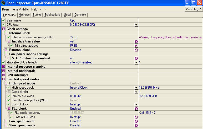
Am I already doing something wrong here? Because the generated clock setup code is this:
/* System clock initialization */ /* ICGC1: HGO=0,RANGE=1,REFS=0,CLKS1=0,CLKS0=1,OSCSTEN=1,LOCD=0,??=0 */ setReg8(ICGC1, 0x4C); /* ICGC2: LOLRE=0,MFD2=0,MFD1=1,MFD0=0,LOCRE=0,RFD2=0,RFD1=0,RFD0=0 */ setReg8(ICGC2, 0x20); if (*(unsigned char*)0xFFBE != 0xFF) { /* Test if the device trim value is stored on the specified address */ ICGTRM = *(unsigned char*)0xFFBE; /* Initialize ICGTRM register from a non volatile memory */ } while(!ICGS1_LOCK) { /* Wait */ }
If I am not misstaken, this gets me prescaler P = 1, Multiplier N = 8 and Divider R = 1
According to the reference manual, page 186, Eqn 10-5, this gets me a bus clock of
fICGOUT = (fIRG / 7) * P * N / R
P = 1, N = 8, R = 1, fIRG = 226.5 kHz
thus
flCGOUT = 226.5kHz / 7 * 8 = 258kHz
In fact, I can verify this bus frequency by a simple software loop that toggles a pin. Obivously it's 1/32 of what I want.
So, did I setup anything wrong in PE here or is it a PE problem? Because I am not sure what steps to take, I wouldnt want to go without PE on this project, since it sets up a whole bunch of other stuff for me, but I can not manually correct the generated code of course, since it would get overwritten all the time.
Would it be a safe alternative to just setup the clock "manually" after the call to PE_low_level_init(); then?
I do hope though that I am just overlooking something obvious in the setup.
Regards,
Sven
Solved! Go to Solution.
- Mark as New
- Bookmark
- Subscribe
- Mute
- Subscribe to RSS Feed
- Permalink
- Report Inappropriate Content
I had to look into this again and just wanted to post the results: The error is not 1/32 but 1/64 since the equation results in the cpu clock (not the bus clock).
The error is simply due to PE setting the RANGE bit in the ICGC1 register, so that the prescaler is set to 1 instead of 64.
This is clearly a PE error and i verified this with the latest CW 6.3 that comes with PE 3.07. I am going to file a service request on this.
The workaround is simple, since the clock can be changed anytime I just copy the PE code to the beginning of my main() function and set the RANGE bit correctly (to zero, so setReg8(ICGC1, 0x0C); )
Regards, Sven
- Mark as New
- Bookmark
- Subscribe
- Mute
- Subscribe to RSS Feed
- Permalink
- Report Inappropriate Content
Hello,
I have not reproduced such behaviour in PE V3.07 in CW V6.3 and I think that initialization code genearted by ProcessorExpert (PE) for Internal clock is correct and correspond to PE documentation and RM of MC9S08AC128.
The correct equation for calculation FLL clock for your settings is: FLL clock = 226,5 / 7 * 64 * 8/1. Please note that in case that Internal clock is selected as clock source the FLL is running in FLL engaged internal (FEI) mode and in this case the value of RANGE bit is ignored and is considered as RANGE = 64 that correspond to P = 64.
For more details please find attached description of RANGE bit.
I have also checked your workaround and I think that it is incorect because RANGE bit is only write-once bit.
In case your problem persist we would need a simple project to reproduced it.
best regards
Vojtech Filip
Processor Expert Support Team
- Mark as New
- Bookmark
- Subscribe
- Mute
- Subscribe to RSS Feed
- Permalink
- Report Inappropriate Content
Hello Vojtech,
Yes, you are right, the manual says clearly that P is 64 in FEI mode and that the RANGE bit only applies in FEE mode.
The RM might be a little ambigous here in that it also says in the example code in 10.5.4, pg. 203 that RANGE needs to be set to zero to configure the oscillator for low frequency range and it also says in the table in 10.4.10 (Clock mode requirements, pg. 196) that no matter which mode you come from, if you want to switch to FEI mode, the RANGE bit must always be set to zero.
However I've gone through this with support already and they can't reproduce the issue either. Dunno why it worked for me, I might just have screwed up somewhere along the line so that something completely different caused my results, sorry.
Regards,
Sven