
- NXP Forums
- Product Forums
- General Purpose MicrocontrollersGeneral Purpose Microcontrollers
- i.MX Forumsi.MX Forums
- QorIQ Processing PlatformsQorIQ Processing Platforms
- Identification and SecurityIdentification and Security
- Power ManagementPower Management
- MCX Microcontrollers
- S32G
- S32K
- S32V
- MPC5xxx
- Other NXP Products
- Wireless Connectivity
- S12 / MagniV Microcontrollers
- Powertrain and Electrification Analog Drivers
- Sensors
- Vybrid Processors
- Digital Signal Controllers
- 8-bit Microcontrollers
- ColdFire/68K Microcontrollers and Processors
- PowerQUICC Processors
- OSBDM and TBDML
-
- Solution Forums
- Software Forums
- MCUXpresso Software and ToolsMCUXpresso Software and Tools
- CodeWarriorCodeWarrior
- MQX Software SolutionsMQX Software Solutions
- Model-Based Design Toolbox (MBDT)Model-Based Design Toolbox (MBDT)
- FreeMASTER
- eIQ Machine Learning Software
- Embedded Software and Tools Clinic
- S32 SDK
- S32 Design Studio
- Vigiles
- GUI Guider
- Zephyr Project
- Voice Technology
- Application Software Packs
- Secure Provisioning SDK (SPSDK)
- Processor Expert Software
-
- Topics
- Mobile Robotics - Drones and RoversMobile Robotics - Drones and Rovers
- NXP Training ContentNXP Training Content
- University ProgramsUniversity Programs
- Rapid IoT
- NXP Designs
- SafeAssure-Community
- OSS Security & Maintenance
- Using Our Community
-
-
- Home
- :
- General Purpose Microcontrollers
- :
- LPC Microcontrollers
- :
- Get the register value of a peripheral device using the SPI driver?
Get the register value of a peripheral device using the SPI driver?
- Subscribe to RSS Feed
- Mark Topic as New
- Mark Topic as Read
- Float this Topic for Current User
- Bookmark
- Subscribe
- Mute
- Printer Friendly Page
Get the register value of a peripheral device using the SPI driver?
- Mark as New
- Bookmark
- Subscribe
- Mute
- Subscribe to RSS Feed
- Permalink
- Report Inappropriate Content
I m having a little difficulty trying to return a register value from a SPI device connected to an LPC5411 board using the fsl_spi.c driver. From looking at the scope I seem to have clock and MOSI signals but I don't think I m getting anything back on the MISO line. I have attached the screen grabs of the scope. I have been working with examples provided by the following sdk. SDK_2.2.1_LPCXpresso54114. I m a little uncertain if slave code in the example spi_polling_transfer.c is necessary when talking to an external device. My assumption is that i can just use the SPI_MasterTransferBlocking() function to send a byte value and the device just returns the requested register value. The code is as follows. Note: I m using a GPIO pin for the slave select line where its pulled low when writing and pulled high when finished writing to device. So I have a few questions.
• If I m not using slave select using masterConfig.sselNum but instead use a GPIO pin, does the fsl_spi need to know this?,
• Can a single byte value be sent via SPI_MasterTransferBlocking() and should this automatically fill the rxData array or is a dummy byte necessary?
• Can slave code be ignored? Is the SPI_SlaveInit() code necessary?
Any help would be greatly appreciated. Thanks.
#define EXAMPLE_SPI_MASTER SPI0
#define EXAMPLE_SPI_MASTER_IRQ FLEXCOMM0_IRQn
#define EXAMPLE_SPI_MASTER_CLK_SRC kCLOCK_Flexcomm0
#define EXAMPLE_SPI_MASTER_CLK_FREQ CLOCK_GetFreq(kCLOCK_Flexcomm0)
#define EXAMPLE_SPI_SLAVE SPI0
#define EXAMPLE_SPI_SLAVE_IRQ FLEXCOMM0_IRQn
#define EXAMPLE_SPI_SSEL 2
#define BUFFER_SIZE (16)
static uint8_t srcBuff[2];
static uint8_t destBuff[BUFFER_SIZE];
{
spi_master_config_t userConfig = {0};
uint32_t srcFreq = 0;
uint32_t i = 0;
uint32_t err = 0;
spi_transfer_t xfer = {0};
status_t xferStatus = kStatus_Success;
// uint32_t err = 0U;
/* attach 12 MHz clock to FLEXCOMM0 (debug console) */
CLOCK_AttachClk(BOARD_DEBUG_UART_CLK_ATTACH);
CLOCK_AttachClk(kFRO12M_to_FLEXCOMM0);
RESET_PeripheralReset(kFC0_RST_SHIFT_RSTn);
BOARD_InitPins();
BOARD_BootClockFROHF48M();
BOARD_InitDebugConsole();
GPIO_Configuration();
userConfig.enableLoopback = false;
userConfig.enableMaster = true;
userConfig.polarity = kSPI_ClockPolarityActiveHigh;
userConfig.phase = kSPI_ClockPhaseFirstEdge;
userConfig.direction = kSPI_MsbFirst;
userConfig.baudRate_Bps = 500000U;
srcFreq = EXAMPLE_SPI_MASTER_CLK_FREQ;
SPI_MasterInit(EXAMPLE_SPI_MASTER, &userConfig, srcFreq);
srcBuff[1] = 0x00;
/*Start Transfer*/
xfer.txData = srcBuff;
xfer.rxData = destBuff;
xfer.dataSize = sizeof(destBuff);
while(1)
{
SPI_CS_Low();
xferStatus = SPI_MasterTransferBlocking(EXAMPLE_SPI_MASTER, &xfer);
SPI_CS_High();
if( kStatus_Success == xferStatus )
{
testVal++;
}
for(uint32_t i = 100000; i != 0; i--);
}
while (1)
{
}
}
//Enable CS for pressure sensor.
const gpio_pin_config_t port0_pin10_gpio_config = {kGPIO_DigitalOutput,0,};
GPIO_PinInit(GPIO, PORT0_IDX, PIN10_IDX, &port0_pin10_gpio_config);
}
//Enable CS for pressure sensor.
const gpio_pin_config_t port0_pin10_gpio_config = {kGPIO_DigitalOutput,1,};
GPIO_PinInit(GPIO, PORT0_IDX, PIN10_IDX, &port0_pin10_gpio_config);
}
- Mark as New
- Bookmark
- Subscribe
- Mute
- Subscribe to RSS Feed
- Permalink
- Report Inappropriate Content
Hi Ronan,
Answer your several questions:
1 If I m not using slave select using masterConfig.sselNum but instead use a GPIO pin, does the fsl_spi need to know this?,
Answer: If you use the different GPIO pin as the SPI_CS pin, which is not the SPI module SPI_CS function, you don't need to let the fsl_spi know, it's OK to send out the correct SPI data.
2 Can a single byte value be sent via SPI_MasterTransferBlocking() and should this automatically fill the rxData array or is a dummy byte necessary?
Answer: Of course, you can send just one byte value, take an example:
xfer.txData = srcBuff;
xfer.dataSize = 1;
xfer.rxData = destBuff;
xfer.configFlags |= kSPI_FrameAssert;
SPI_MasterTransferBlocking(EXAMPLE_SPI_MASTER, &xfer);
You just need to define the xfer.dataSize=1. About the rxdata, you enable the receive, the code will fill in the xfer.rxData.
3 Can slave code be ignored? Is the SPI_SlaveInit() code necessary?
Answer: Of course, you can ignored, the KSDK SPI sample contains both master and slave in one project, if you just need to have master, you can delete the slave code.
Wish it helps you!
Have a great day,
Kerry
-----------------------------------------------------------------------------------------------------------------------
Note: If this post answers your question, please click the Correct Answer button. Thank you!
-----------------------------------------------------------------------------------------------------------------------
- Mark as New
- Bookmark
- Subscribe
- Mute
- Subscribe to RSS Feed
- Permalink
- Report Inappropriate Content
Hi Kerry,
Thank you for the response. I was still having problems getting register values. I was receiving a value of 255 and sometimes 242, which corresponds to 0xff and 0xf2. This wasn't the value I was expecting. When you say "About the rxdata, you enable the receive, the code will fill in the xfer.rxData." Is there a setting to enable receive and send? I remember from using I2C that you had to specify the I2C direction. eg masterXfer.direction = kI2C_Write; and masterXfer.direction = kI2C_Read; . Is there something similar setting with SPI? Perhaps my problem has to do with my pinmux setting. I was able to run the example code with the default pin configuration but for my project I need to use port 0 pin 0 and port 0 pin 1 for MOSI, MISO. In addition I have my clock on port 0 pin 4. Am I correct with selecting the pull up function below for MOSI, MISO. Here is my pin configuration. Is there anything wrong with it?
CLOCK_EnableClock(kCLOCK_Iocon);
IOCON_PIO_FUNC1 | /* Pin is configured as FC0_RXD_SDA_MOSI */
IOCON_PIO_MODE_PULLUP | /* Selects pull-up function */
// IOCON_PIO_MODE_INACT | /* No addition pin function */
IOCON_PIO_INV_DI | /* Input function is not inverted */
IOCON_PIO_DIGITAL_EN | /* Enables digital function */
IOCON_PIO_INPFILT_OFF | /* Input filter disabled */
IOCON_PIO_SLEW_STANDARD | /* Standard mode, output slew rate control is enabled */
IOCON_PIO_OPENDRAIN_DI /* Open drain is disabled */
);
IOCON_PinMuxSet(IOCON, PORT0_IDX, PIN0_IDX, port0_pin0_config); /* PORT0 PIN0 (coords: 31) is configured as FC0_RXD_SDA_MOSI */
const uint32_t port0_pin1_config = (
IOCON_PIO_FUNC1 | /* Pin is configured as FC0_TXD_SCL_MISO */
IOCON_PIO_MODE_PULLUP | /* Selects pull-up function */
//IOCON_PIO_MODE_INACT | /* No addition pin function */
IOCON_PIO_INV_DI | /* Input function is not inverted */
IOCON_PIO_DIGITAL_EN | /* Enables digital function */
IOCON_PIO_INPFILT_OFF | /* Input filter disabled */
IOCON_PIO_SLEW_STANDARD | /* Standard mode, output slew rate control is enabled */
IOCON_PIO_OPENDRAIN_DI /* Open drain is disabled */
);
IOCON_PinMuxSet(IOCON, PORT0_IDX, PIN1_IDX, port0_pin1_config); /* PORT0 PIN1 (coords: 32) is configured as FC0_TXD_SCL_MISO */
IOCON_PIO_FUNC1 | /* Pin is configured as CLK */
IOCON_PIO_MODE_PULLUP | /* Selects pull-up function */
IOCON_PIO_INV_DI | /* Input function is not inverted */
IOCON_PIO_DIGITAL_EN | /* Enables digital function */
IOCON_PIO_INPFILT_OFF | /* Input filter disabled */
IOCON_PIO_SLEW_STANDARD | /* Standard mode, output slew rate control is enabled */
IOCON_PIO_OPENDRAIN_DI /* Open drain is disabled */
);
IOCON_PinMuxSet(IOCON, PORT0_IDX, PIN4_IDX, port0_pin4_config); /* PORT0 PIN4 (coords: 38) is configured as FC3_SSEL2 */
Thank you.
- Mark as New
- Bookmark
- Subscribe
- Mute
- Subscribe to RSS Feed
- Permalink
- Report Inappropriate Content
And just to add. I have the SPI set up on flexcomm 0 so I tried to match this with the pin setup using IOCON_PIO_FUNC1 | for each pin.
- Mark as New
- Bookmark
- Subscribe
- Mute
- Subscribe to RSS Feed
- Permalink
- Report Inappropriate Content
Hi Ronan,
Could you please send me a picture contains the SPI bus: spi_clk, spi_mosi, spi_miso, spi_cs together?
It will be useful to my analysis, from your description, it seems the MISO data is not correct, so I need to check the spi bus at first, if the spi bus data is correct, then the code may have problem, otherwise, if MISO wire don't have data, it means your slaver didn't give out the correct data.
Please give me the spi wave with 4-CH oscilloscope, or the logic analyzer.
Have a great day,
Kerry
-----------------------------------------------------------------------------------------------------------------------
Note: If this post answers your question, please click the Correct Answer button. Thank you!
-----------------------------------------------------------------------------------------------------------------------
- Mark as New
- Bookmark
- Subscribe
- Mute
- Subscribe to RSS Feed
- Permalink
- Report Inappropriate Content
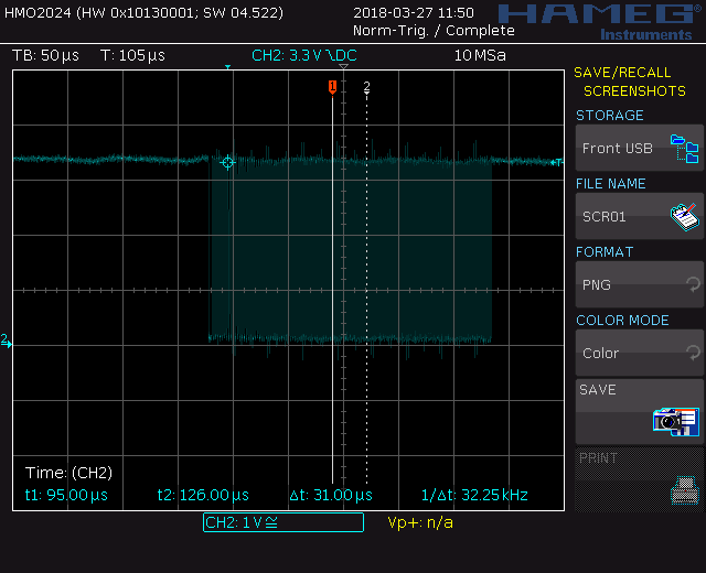
Hi Kerry,
I have attached a picture of the 4 channels together. Channel 1(yellow) is the SPI clock, channel 2(blue) is the SPI MOSI, channel 3(purple) is the chip select and channel 4(green) is the SPI MISO line. It appears the chip select is pulling low when it should be when there are pulses from the clock. Also, changing the byte value on the MOSI line seems to be changing correctly.
I did notice that my clock signal is only 8 cycles. The device I'm using is a pressure sensor called LPS22HBTR. It seems that the clock should be 16 cycles but i m not sure how I make the clock do this.
Thank you

- Mark as New
- Bookmark
- Subscribe
- Mute
- Subscribe to RSS Feed
- Permalink
- Report Inappropriate Content
Hi Ronan,
Your wave seems have the problem, please download the newest LPC54114 SDK2.3.0 from this link:
Welcome | MCUXpresso SDK Builder
After you download SDK_2.3.0_LPCXpresso54114, please go this folder :
SDK_2.3.0_LPCXpresso54114\boards\lpcxpresso54114\driver_examples\spi\polling_b2b_transfer\master
I run it, didn't connect the slave, you can find the master SPI wave is:

Then, you just need to modify the xfer.dataSize, and srcBuff data to meet your slave demand, then test it.
Wish it helps you!
Have a great day,
Kerry
-----------------------------------------------------------------------------------------------------------------------
Note: If this post answers your question, please click the Correct Answer button. Thank you!
-----------------------------------------------------------------------------------------------------------------------
- Mark as New
- Bookmark
- Subscribe
- Mute
- Subscribe to RSS Feed
- Permalink
- Report Inappropriate Content
SCR01 --> clock,
SCR02 --> MOSI,
SCR03 --> MISO