
- NXP Forums
- Product Forums
- General Purpose MicrocontrollersGeneral Purpose Microcontrollers
- i.MX Forumsi.MX Forums
- QorIQ Processing PlatformsQorIQ Processing Platforms
- Identification and SecurityIdentification and Security
- Power ManagementPower Management
- MCX Microcontrollers
- S32G
- S32K
- S32V
- MPC5xxx
- Other NXP Products
- Wireless Connectivity
- S12 / MagniV Microcontrollers
- Powertrain and Electrification Analog Drivers
- Sensors
- Vybrid Processors
- Digital Signal Controllers
- 8-bit Microcontrollers
- ColdFire/68K Microcontrollers and Processors
- PowerQUICC Processors
- OSBDM and TBDML
-
- Solution Forums
- Software Forums
- MCUXpresso Software and ToolsMCUXpresso Software and Tools
- CodeWarriorCodeWarrior
- MQX Software SolutionsMQX Software Solutions
- Model-Based Design Toolbox (MBDT)Model-Based Design Toolbox (MBDT)
- FreeMASTER
- eIQ Machine Learning Software
- Embedded Software and Tools Clinic
- S32 SDK
- S32 Design Studio
- Vigiles
- GUI Guider
- Zephyr Project
- Voice Technology
- Application Software Packs
- Secure Provisioning SDK (SPSDK)
- Processor Expert Software
-
- Topics
- Mobile Robotics - Drones and RoversMobile Robotics - Drones and Rovers
- NXP Training ContentNXP Training Content
- University ProgramsUniversity Programs
- Rapid IoT
- NXP Designs
- SafeAssure-Community
- OSS Security & Maintenance
- Using Our Community
-
- Cloud Lab Forums
-
- Home
- :
- Product Forums
- :
- Other NXP Products
- :
- DIY design for simple wireless charging system
DIY design for simple wireless charging system
- Subscribe to RSS Feed
- Mark Topic as New
- Mark Topic as Read
- Float this Topic for Current User
- Bookmark
- Subscribe
- Mute
- Printer Friendly Page
DIY design for simple wireless charging system
- Mark as New
- Bookmark
- Subscribe
- Mute
- Subscribe to RSS Feed
- Permalink
- Report Inappropriate Content
I read an electronic magazine in which there is a report on diy design for simple wireless charging system. After reading, I became interested in wireless charging system. So I searched some related materials and information about this topic. Today I come to this forum to turn to you to discuss my understandings are appropriate.
Here are my personal understandings:
The wireless charging system mainly uses the electromagnetic induction principle. Electromagnetic induction program is the use of transformer principle, through the beginning and secondary coil induction to achieve the transmission of electricity. Based on this way the wireless power transmission system has three main components, namely, energy transmitter, contactless transformer, energy receiver. When the transmission coil is connected to an alternating current, the current will form an alternating magnetic field in the surrounding medium, and the induced electromotive force generated in the receiving coil can be supplied to the mobile device or the battery is charged. This program is characterized by the energy receiver and secondary coil connected, flexible movement, the circuit is simple, easy to implement, can be used for the distance is not high but does not require mechanical and electrical connections of the occasion.
Selection of wireless power supply circuit
CD4069 crystal oscillator circuit and power field effect of the composition of the wireless charging circuit.
The circuit is shown in Figure (6)
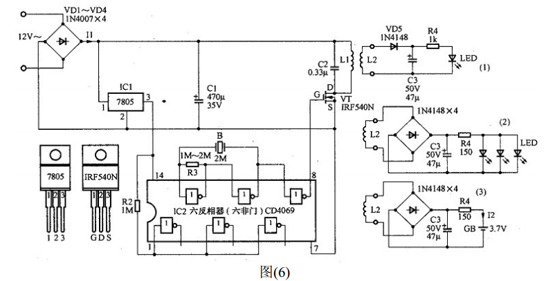
The charge circuit of the CD400 series of CMOS circuits when the limit voltage of 18v, unstable AC 12v voltage rectifier filter after the no-load voltage may exceed 18v, so the CD4069 power supply voltage is provided by the three-terminal regulator IC 7805. CMOS circuit all the unused input connected to the appropriate logic level, the crystal oscillator connected to a single-stage oscillator, the oscillation output by the secondary buffer to the power FET after the gate G, began to protect the FET, the gate Pole circuit set on the bias and leakage circuit to ensure the stability of the circuit work.
3, The experimental steps
Follow the link below to connect the line and connect it for debugging.
4. The summary for designation
The experiment can light the light-emitting diode and rechargeable battery can charge, basically meet the experimental requirements but the transmission coil and the receiving coil between the sensing distance is not too long, so there is room for improvement. For example, a power amplifier circuit may be connected to the transmitting circuit to increase the power of the transmitting coil.
Ps: Excuse me if I was wrong in words or expressions as I am a green hand in the field of wireless charging system. I need continual learnings.
What is your idea ? Do you agree with my ideas ? Any of your ideas would be highly appreciated.
May someone would like to help ?
thanks in advance