
- Forums
- Product Forums
- General Purpose MicrocontrollersGeneral Purpose Microcontrollers
- i.MX Forumsi.MX Forums
- QorIQ Processing PlatformsQorIQ Processing Platforms
- Identification and SecurityIdentification and Security
- Power ManagementPower Management
- Wireless ConnectivityWireless Connectivity
- RFID / NFCRFID / NFC
- Advanced AnalogAdvanced Analog
- Neural Processing UnitsNeural Processing Units
- MCX Microcontrollers
- S32G
- S32K
- S32V
- MPC5xxx
- Other NXP Products
- S12 / MagniV Microcontrollers
- Powertrain and Electrification Analog Drivers
- Sensors
- Vybrid Processors
- Digital Signal Controllers
- 8-bit Microcontrollers
- ColdFire/68K Microcontrollers and Processors
- PowerQUICC Processors
- OSBDM and TBDML
- S32M
- S32Z/E
-
- Solution Forums
- Software Forums
- MCUXpresso Software and ToolsMCUXpresso Software and Tools
- CodeWarriorCodeWarrior
- MQX Software SolutionsMQX Software Solutions
- Model-Based Design Toolbox (MBDT)Model-Based Design Toolbox (MBDT)
- FreeMASTER
- eIQ Machine Learning Software
- Embedded Software and Tools Clinic
- S32 SDK
- S32 Design Studio
- GUI Guider
- Zephyr Project
- Voice Technology
- Application Software Packs
- Secure Provisioning SDK (SPSDK)
- Processor Expert Software
- Generative AI & LLMs
-
- Topics
- Mobile Robotics - Drones and RoversMobile Robotics - Drones and Rovers
- NXP Training ContentNXP Training Content
- University ProgramsUniversity Programs
- Rapid IoT
- NXP Designs
- SafeAssure-Community
- OSS Security & Maintenance
- Using Our Community
-
- Cloud Lab Forums
-
- Knowledge Bases
- ARM Microcontrollers
- i.MX Processors
- Identification and Security
- Model-Based Design Toolbox (MBDT)
- QorIQ Processing Platforms
- S32 Automotive Processing Platform
- Wireless Connectivity
- CodeWarrior
- MCUXpresso Suite of Software and Tools
- MQX Software Solutions
- RFID / NFC
- Advanced Analog
- Neural Processing Units
-
- NXP Tech Blogs
- Home
- :
- MCUXpresso Software and Tools
- :
- LPCXpresso IDE
- :
- Lpc1114 isp
Lpc1114 isp
Turn on suggestions
Auto-suggest helps you quickly narrow down your search results by suggesting possible matches as you type.
Options
- Subscribe to RSS Feed
- Mark Topic as New
- Mark Topic as Read
- Float this Topic for Current User
- Bookmark
- Subscribe
- Mute
- Printer Friendly Page
Lpc1114 isp
06-15-2016
04:32 PM
15,428 Views
NXP Employee
- Mark as New
- Bookmark
- Subscribe
- Mute
- Subscribe to RSS Feed
- Permalink
- Report Inappropriate Content
Content originally posted in LPCWare by Kartman on Mon Oct 29 04:20:59 MST 2012
I've just built a pcb of my own design with a LPC1114-303 device on it. I'm trying to program it via a LPC1769 Lpcxpresso board via the isp cable. I've cut the tracks on J4 and used the lpc-link side on other boards (lpc1769 based).
Apart from 0V, I've got SWDIO, SWCLK and NRST wired to the lpc1114. Note that I have no crystal on the LPC1114. When I try to load code into it, I get an error message from lpcxpresso gui V4.3.2
"Error lauching debug
02:Failed on connect: Ee(07): Bad ack returned from status - wire error
I might have wiring issues as I'm using the FHI package part which is 'fun' to solder, but all things being equal, should I be able to expect this setup to work?
14 Replies
06-15-2016
04:33 PM
15,264 Views
NXP Employee
- Mark as New
- Bookmark
- Subscribe
- Mute
- Subscribe to RSS Feed
- Permalink
- Report Inappropriate Content
Content originally posted in LPCWare by LabRat on Mon Oct 20 08:37:27 MST 2014
Quote: Lukman_Bawafi
What could be improved?
Calibrate it....
http://www.dummies.com/how-to/content/measure-electronic-waves-how-to-calibrate-an-oscil.html
Quote: Lukman_Bawafi
What could be improved?
Calibrate it....
http://www.dummies.com/how-to/content/measure-electronic-waves-how-to-calibrate-an-oscil.html
06-15-2016
04:33 PM
15,264 Views
NXP Employee
- Mark as New
- Bookmark
- Subscribe
- Mute
- Subscribe to RSS Feed
- Permalink
- Report Inappropriate Content
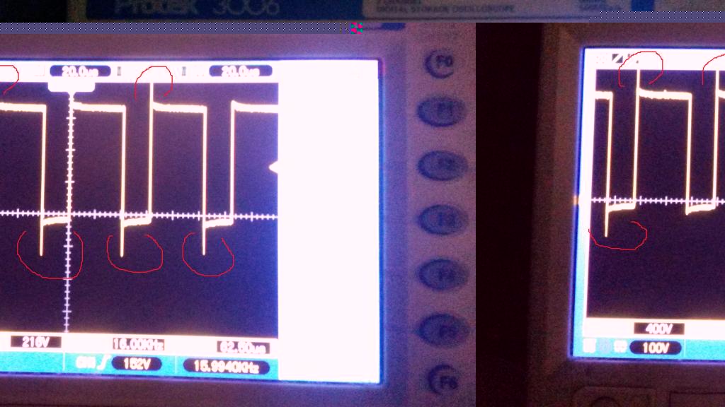
Content originally posted in LPCWare by Lukman_Bawafi on Mon Oct 20 07:26:21 MST 2014
Hello
I create a project using LPCXpresso LPC1115 Rev A.
I utilize SPI to read 16KHz WAV files from the MicroSD, then channeled through the voice data out PWM signal. The problem is, the sound is not clean because of the interference noise, after I see in osciloscop pwm signal produced is not good. signal can be seen in the picture at attachment. What could be improved?
06-15-2016
04:33 PM
15,264 Views
NXP Employee
- Mark as New
- Bookmark
- Subscribe
- Mute
- Subscribe to RSS Feed
- Permalink
- Report Inappropriate Content
Content originally posted in LPCWare by NXP_Paul on Mon Oct 20 06:14:07 MST 2014
Hello Lukman
Since this is a new topic, unrelated to the LPC1114 ISP, in the future, please start a new topic when the subject is changed.
Unfortunately, I don't understand your question. Are you questioning a disturbance of the PWM signal caused by the resetting of the TC?
Please provide more detail regarding the problem you are experiencing.
Thanks
Paul
06-15-2016
04:33 PM
15,264 Views
NXP Employee
- Mark as New
- Bookmark
- Subscribe
- Mute
- Subscribe to RSS Feed
- Permalink
- Report Inappropriate Content
Content originally posted in LPCWare by Lukman_Bawafi on Mon Oct 20 04:41:32 MST 2014
Hello
I create a project player wav file using 16KHz PWM, the source files from microSD. The sound was out but no disturbing noise (hum). Pwm signal when I look at osciloskop no disturbance during the process of resetting the TC (timer counter). How do I solve this?
RC filter already exists.
Thanks
Lukman
06-15-2016
04:33 PM
15,264 Views
NXP Employee
- Mark as New
- Bookmark
- Subscribe
- Mute
- Subscribe to RSS Feed
- Permalink
- Report Inappropriate Content
Content originally posted in LPCWare by Kartman on Wed Oct 31 06:01:01 MST 2012
As Borat says 'Great Success!'
With the device properly soldered, it decided to work. The next challenge was the clock selection - a little search here yielded the correct result.
I am happy and can sleep now! Thanks for all of your assistance.
What have I learned about soldering the HVQFN 5x5 package (FHI)? It helps to have a soldering iron with a very small tip. My two original techniques were to blob up the pads on the chip itself and hot air reflow- not too successful and to blob up the pcb, again not too successful. Maybe blob up both the pcb and the package might be good but drag soldering the pads with flux gel and a small soldering tip seems to be the successful method at this time.
06-15-2016
04:33 PM
15,264 Views
NXP Employee
- Mark as New
- Bookmark
- Subscribe
- Mute
- Subscribe to RSS Feed
- Permalink
- Report Inappropriate Content
Content originally posted in LPCWare by tha on Tue Oct 30 12:43:14 MST 2012
From the user manual for the xtal pins:
"When the system oscillator is not used, connect XTALIN and XTALOUT as follows: XTALIN can be left floating or can be grounded (grounding is preferred to reduce susceptibility to noise). XTALOUT should be left floating.
From the user manual for the xtal pins:
"When the system oscillator is not used, connect XTALIN and XTALOUT as follows: XTALIN can be left floating or can be grounded (grounding is preferred to reduce susceptibility to noise). XTALOUT should be left floating.
06-15-2016
04:33 PM
15,264 Views
NXP Employee
- Mark as New
- Bookmark
- Subscribe
- Mute
- Subscribe to RSS Feed
- Permalink
- Report Inappropriate Content
Content originally posted in LPCWare by Kartman on Tue Oct 30 00:20:10 MST 2012
Rob, this is my second lot of pcbs. The first lot got toasted in a Australia Post truck accident. It's also the second lot of LPC1114s. The first lot were the 7x7mm HVQFN then I realised that there were two sizes of HVQFN - I designed the board using the 5x5mm. So this project has had a shaky start. I got the boards resoldered earlier and tried to program one - same problem. I'll have to look deeper. I'll try ISP as well as I put a pad there.
Another question - I've left the XTAL pads floating. Kosher?
06-15-2016
04:33 PM
15,264 Views
NXP Employee
- Mark as New
- Bookmark
- Subscribe
- Mute
- Subscribe to RSS Feed
- Permalink
- Report Inappropriate Content
Content originally posted in LPCWare by graynomad on Mon Oct 29 21:55:19 MST 2012
I still use ISP, old habits die hard :)
This is my first PCB design using an LPC, it looks simple enough but there's always a gotcha or two. Hopefully I've caught them all before I get the boards made.
I still use ISP, old habits die hard :)
This is my first PCB design using an LPC, it looks simple enough but there's always a gotcha or two. Hopefully I've caught them all before I get the boards made.
06-15-2016
04:33 PM
15,264 Views
NXP Employee
- Mark as New
- Bookmark
- Subscribe
- Mute
- Subscribe to RSS Feed
- Permalink
- Report Inappropriate Content
Content originally posted in LPCWare by Kartman on Mon Oct 29 20:07:15 MST 2012
Gents, just to clarify, I am referring to SWD as opposed to ISP ( just need to come up to speed with the acronyms).
Rob - my connections are the same (except for the 3v3). Moonlighting from 'Freaks! Of course. This is one of the other few forums where you get sensible replies.
I'm having one of the guys at the office redo the soldering. For those who are not aware, the FHI package is 0.5mm CSP. This is my first attempt at hand soldering them. My guess is one of the vcc pins was not connected. All the other pins measured a diode drop and no short to 0v.
i just wanted to make sure there wasn't some software version or other problem that might stop things from working. My other project using a LPC1769 worked out of the box with the LPC-LINK.
Thanks for the assistance.
06-15-2016
04:33 PM
15,264 Views
NXP Employee
- Mark as New
- Bookmark
- Subscribe
- Mute
- Subscribe to RSS Feed
- Permalink
- Report Inappropriate Content
Content originally posted in LPCWare by daniel.widyanto on Mon Oct 29 19:47:16 MST 2012
Hi graynomad,
Pin 1 (VTRef) is optional, to detect the board's logic level and adjust the JTAG voltage logic, if the JTAG supports it.
So no need to worry about it will do any harm for your board.
Hi graynomad,
Pin 1 (VTRef) is optional, to detect the board's logic level and adjust the JTAG voltage logic, if the JTAG supports it.
So no need to worry about it will do any harm for your board.
06-15-2016
04:33 PM
15,264 Views
NXP Employee
- Mark as New
- Bookmark
- Subscribe
- Mute
- Subscribe to RSS Feed
- Permalink
- Report Inappropriate Content
Content originally posted in LPCWare by graynomad on Mon Oct 29 16:56:58 MST 2012
Hi Kartman, moonlighting from Freaks are we :)
I'm about to start laying out a board and plan to do the same as you. Here is my circuit
[IMG]http://www.robgray.com/temp/LPC-ISP.jpg[/IMG]
Which I provide as a reference, essentially to see if we have the same thing.
I will add pull up resistors on the signals and also according to the CR page linked to by Zero the 3v3 is not required.
So can someone verify that this is correct? Does the 3v3 do any harm or should I remove it?
06-15-2016
04:33 PM
15,264 Views
NXP Employee
- Mark as New
- Bookmark
- Subscribe
- Mute
- Subscribe to RSS Feed
- Permalink
- Report Inappropriate Content
Content originally posted in LPCWare by Ex-Zero on Mon Oct 29 16:25:09 MST 2012
Quote: Kartman
1. Is a crystal necessary on the lpc1114 in order to do ISP?
Are we talking about ISP or SWD :confused:
Both don't need a crystal, they work with IRC.
Quote: Kartman
1. Is a crystal necessary on the lpc1114 in order to do ISP?
2. The LPCXPRESSO 1768 LPC-LINK will work with the lpc1114?
Although there are different LPC-Links (especially different power supplies) they all work with all possible MCUs :)
So your problem is not caused by this things ;)
Quote: Kartman
1. Is a crystal necessary on the lpc1114 in order to do ISP?
Are we talking about ISP or SWD :confused:
Both don't need a crystal, they work with IRC.
Quote: Kartman
1. Is a crystal necessary on the lpc1114 in order to do ISP?
2. The LPCXPRESSO 1768 LPC-LINK will work with the lpc1114?
Although there are different LPC-Links (especially different power supplies) they all work with all possible MCUs :)
So your problem is not caused by this things ;)
06-15-2016
04:33 PM
15,264 Views
NXP Employee
- Mark as New
- Bookmark
- Subscribe
- Mute
- Subscribe to RSS Feed
- Permalink
- Report Inappropriate Content
Content originally posted in LPCWare by Kartman on Mon Oct 29 16:09:48 MST 2012
The schematic I'm reasonably sure is correct, but as to whether all the connections are sound due to the difficulty in soldering the FHI package. Nevertheless,
1. Is a crystal necessary on the lpc1114 in order to do ISP?
2. The LPCXPRESSO 1768 LPC-LINK will work with the lpc1114?
At the moment I'm building a prototype and there are a number of unknowns. I'm trying to minimise these. It is probably bad solder connections causing me problems. I've used a multimeter to measure the diode junctions on most of the pins. Measuring the power pin connections are a little more difficult.
06-15-2016
04:33 PM
15,264 Views
NXP Employee
- Mark as New
- Bookmark
- Subscribe
- Mute
- Subscribe to RSS Feed
- Permalink
- Report Inappropriate Content
Content originally posted in LPCWare by Ex-Zero on Mon Oct 29 04:30:32 MST 2012
SWD connection is described in #9 of http://knowledgebase.nxp.com/showthread.php?p=8311
If you are not sure about correct wiring, just post schematic of SWD / RESET / ISP pins ;)
SWD connection is described in #9 of http://knowledgebase.nxp.com/showthread.php?p=8311
If you are not sure about correct wiring, just post schematic of SWD / RESET / ISP pins ;)