
- NXP Forums
- Product Forums
- General Purpose MicrocontrollersGeneral Purpose Microcontrollers
- i.MX Forumsi.MX Forums
- QorIQ Processing PlatformsQorIQ Processing Platforms
- Identification and SecurityIdentification and Security
- Power ManagementPower Management
- MCX Microcontrollers
- S32G
- S32K
- S32V
- MPC5xxx
- Other NXP Products
- Wireless Connectivity
- S12 / MagniV Microcontrollers
- Powertrain and Electrification Analog Drivers
- Sensors
- Vybrid Processors
- Digital Signal Controllers
- 8-bit Microcontrollers
- ColdFire/68K Microcontrollers and Processors
- PowerQUICC Processors
- OSBDM and TBDML
-
- Solution Forums
- Software Forums
- MCUXpresso Software and ToolsMCUXpresso Software and Tools
- CodeWarriorCodeWarrior
- MQX Software SolutionsMQX Software Solutions
- Model-Based Design Toolbox (MBDT)Model-Based Design Toolbox (MBDT)
- FreeMASTER
- eIQ Machine Learning Software
- Embedded Software and Tools Clinic
- S32 SDK
- S32 Design Studio
- Vigiles
- GUI Guider
- Zephyr Project
- Voice Technology
- Application Software Packs
- Secure Provisioning SDK (SPSDK)
- Processor Expert Software
-
- Topics
- Mobile Robotics - Drones and RoversMobile Robotics - Drones and Rovers
- NXP Training ContentNXP Training Content
- University ProgramsUniversity Programs
- Rapid IoT
- NXP Designs
- SafeAssure-Community
- OSS Security & Maintenance
- Using Our Community
-
-
- Home
- :
- General Purpose Microcontrollers
- :
- LPC Microcontrollers
- :
- LPC1769 CAN1 bus is not working
LPC1769 CAN1 bus is not working
Turn on suggestions
Auto-suggest helps you quickly narrow down your search results by suggesting possible matches as you type.
Options
- Subscribe to RSS Feed
- Mark Topic as New
- Mark Topic as Read
- Float this Topic for Current User
- Bookmark
- Subscribe
- Mute
- Printer Friendly Page
LPC1769 CAN1 bus is not working
06-15-2016
01:15 PM
1,309 Views
NXP Employee
- Mark as New
- Bookmark
- Subscribe
- Mute
- Subscribe to RSS Feed
- Permalink
- Report Inappropriate Content
Content originally posted in LPCWare by kbalar on Mon Sep 28 09:07:57 MST 2015
Hi,
I am using LPCXpresso LPC1769 board (OM13000) and LPCXpresso LPC11C24 board (OM13012) connected via CAN2 bus.
I ran "periph_can" example on LPC1769 and CAN2 bus communication between these two board is working fine. Both the board can send data to each other via CAN2 bus of LPC1769.
Now same way I try to connect CAN1 bus of LPC1769 to LPC11C24.
the "periph_can" example on LPC1769, I have modified as below to use CAN1 bus. I have change CAN_CTRL_NO to 0 so that I can use CAN1.
#if defined(CHIP_LPC175X_6X)
---#define CAN_CTRL_NO 1
+++#define CAN_CTRL_NO 0
#else
#define CAN_CTRL_NO 0
#endif
#if (CAN_CTRL_NO == 0)
#define LPC_CAN (LPC_CAN1)
#else
#define LPC_CAN (LPC_CAN2)
#endif
I have changed CAN bus connection to LPC11c24 via CAN1 bus of LPC1769.
Then I try to run this example on LPC1769 and try to communicate between this two board.
But this time communication via CAN1 bus is not working.
I have attached can.c of "periph_can" example on LPC1769 and also attached lpc11c24_test.c of LPC11c24 which I am using.
What could be wrong in this?
I am bit new with LPC controllers and CAN bus communication.
Thanks,
KBalar
Note: Same setup and example is working fine on CAN2 bus but nor working on CAN1 bus.
Original Attachment has been moved to: lpc11c24_test.c.zip
Original Attachment has been moved to: can.c.zip
12 Replies
06-15-2016
01:15 PM
1,049 Views
NXP Employee
- Mark as New
- Bookmark
- Subscribe
- Mute
- Subscribe to RSS Feed
- Permalink
- Report Inappropriate Content
Content originally posted in LPCWare by kbalar on Wed Oct 07 01:16:33 MST 2015
Quote: R2D2
So your problem is your hardware and I would recommend to switch to Local self test (Chapter 16.5.8)
and scope your hardware...
Yes it was hardware issue. Two board were sharing common power supply and it was result in power drop for one board. Due to that transreceiver was not working.
Changed power supply and now both CAN bus are working fine.
Thank you for your help.
06-15-2016
01:15 PM
1,049 Views
NXP Employee
- Mark as New
- Bookmark
- Subscribe
- Mute
- Subscribe to RSS Feed
- Permalink
- Report Inappropriate Content
06-15-2016
01:15 PM
1,049 Views
NXP Employee
- Mark as New
- Bookmark
- Subscribe
- Mute
- Subscribe to RSS Feed
- Permalink
- Report Inappropriate Content
Content originally posted in LPCWare by R2D2 on Wed Sep 30 13:36:19 MST 2015
Quote: kbalar
I have attached my entire program with board lib here...
..which is again working without problems here
CAN-Sniffer and Scope are showing the message
So your problem is your hardware and I would recommend to switch to Local self test (Chapter 16.5.8)
and scope your hardware...
Quote: kbalar
I have attached my entire program with board lib here...
..which is again working without problems here
CAN-Sniffer and Scope are showing the message
So your problem is your hardware and I would recommend to switch to Local self test (Chapter 16.5.8)
and scope your hardware...
Chip_CAN_Init(LPC_CAN, LPC_CANAF, LPC_CANAF_RAM); [color=#f00]Chip_CAN_SetMode(LPC_CAN, CAN_SELFTEST_MODE, ENABLE);[/color] Chip_CAN_SetBitRate(LPC_CAN, 500000); Chip_CAN_EnableInt(LPC_CAN, CAN_IER_BITMASK); |
06-15-2016
01:15 PM
1,049 Views
NXP Employee
- Mark as New
- Bookmark
- Subscribe
- Mute
- Subscribe to RSS Feed
- Permalink
- Report Inappropriate Content
Content originally posted in LPCWare by mysepp on Wed Sep 30 11:53:12 MST 2015
What have you connected to your CAN transceiver? Do you have termination?
What have you connected to your CAN transceiver? Do you have termination?
06-15-2016
01:15 PM
1,049 Views
NXP Employee
- Mark as New
- Bookmark
- Subscribe
- Mute
- Subscribe to RSS Feed
- Permalink
- Report Inappropriate Content
Content originally posted in LPCWare by kbalar on Wed Sep 30 09:26:52 MST 2015
I have attached my entire program with board lib here for more information.
Yes in debugging I can see pin muxing for p0.0 and p0.1 is set to function 1.
But program always stuck at below while loop.
SendMsgBuf.ID = CAN_TX_MSG_STD_ID;
SendMsgBuf.DLC = 1;
SendMsgBuf.Type = 0;
SendMsgBuf.Data[0] = 20;
TxBuf = Chip_CAN_GetFreeTxBuf(LPC_CAN);
Chip_CAN_Send(LPC_CAN, TxBuf, &SendMsgBuf);
while ((Chip_CAN_GetStatus(LPC_CAN) & CAN_SR_TCS(TxBuf)) == 0) {}
When entering to this line below is the status of LPC_CAN1
LPC_CAN1LPC_CAN_T *0x40044000
MODvolatile uint32_t0
CMRvolatile uint32_t0
GSRvolatile uint32_t2147483744
ICRconst volatile uint32_t14221440
IERvolatile uint32_t2047
BTRvolatile uint32_t7323649
EWLvolatile uint32_t96
SRconst volatile uint32_t5000288
RXvolatile IP_CAN_001_RX_T{...}
TXLPC_CAN_TX_T [3]0x40044030
TX[0]LPC_CAN_TX_T{...}
TFIvolatile uint32_t65536
TIDvolatile uint32_t512
TDuint32_t [2]0x40044038
TD[0]uint32_t878095124
TD[1]uint32_t305419896
TX[1]LPC_CAN_TX_T{...}
TFIvolatile uint32_t0
TIDvolatile uint32_t0
TDuint32_t [2]0x40044048
TD[0]uint32_t0
TD[1]uint32_t0
TX[2]LPC_CAN_TX_T{...}
TFIvolatile uint32_t0
TIDvolatile uint32_t0
TDuint32_t [2]0x40044058
TD[0]uint32_t0
TD[1]uint32_t0
Thanks,
KBalar
06-15-2016
01:15 PM
1,049 Views
NXP Employee
- Mark as New
- Bookmark
- Subscribe
- Mute
- Subscribe to RSS Feed
- Permalink
- Report Inappropriate Content
Content originally posted in LPCWare by R2D2 on Tue Sep 29 13:11:57 MST 2015
Quote: balarkalpesh@gmail.com
But still I have no success for CAN1 communication.
And is debugger showing RD1 / TD1 function at P0_0 / P0_1 :quest: :quest: :quest:
Quote: balarkalpesh@gmail.com
But still I have no success for CAN1 communication.
And is debugger showing RD1 / TD1 function at P0_0 / P0_1 :quest: :quest: :quest:
06-15-2016
01:15 PM
1,049 Views
NXP Employee
- Mark as New
- Bookmark
- Subscribe
- Mute
- Subscribe to RSS Feed
- Permalink
- Report Inappropriate Content
Content originally posted in LPCWare by kbalar on Tue Sep 29 09:45:15 MST 2015
I have selected function 1 for P0.0 and P0.1 as below
/* Pin muxing configuration */
STATIC const PINMUX_GRP_T pinmuxing[] = {
{0, 0, IOCON_MODE_INACT | IOCON_FUNC1},/* CAN-RD1 */
{0, 1, IOCON_MODE_INACT | IOCON_FUNC1},/* CAN-TD1 */
{0, 4, IOCON_MODE_INACT | IOCON_FUNC2},/* CAN-RD2 */
{0, 5, IOCON_MODE_INACT | IOCON_FUNC2},/* CAN-TD2 */
But still I have no success for CAN1 communication.
Thanks,
Kalpesh Balar
06-15-2016
01:15 PM
1,049 Views
NXP Employee
- Mark as New
- Bookmark
- Subscribe
- Mute
- Subscribe to RSS Feed
- Permalink
- Report Inappropriate Content
Content originally posted in LPCWare by R2D2 on Tue Sep 29 09:05:54 MST 2015
Quote: balarkalpesh@gmail.com
Where can I see CAN1 pin muxing?
Use the debugger :O
Quote: balarkalpesh@gmail.com
How can I verify CAN1 pin muxing is correct or not?
Read User Manual Chapter 8.5.1:
[color=#f00]Pin Function Select register 0 (PINSEL0 - 0x4002 C000) [/color]
Quote: balarkalpesh@gmail.com
Where can I see CAN1 pin muxing?
Use the debugger :O
Quote: balarkalpesh@gmail.com
How can I verify CAN1 pin muxing is correct or not?
Read User Manual Chapter 8.5.1:
[color=#f00]Pin Function Select register 0 (PINSEL0 - 0x4002 C000) [/color]
06-15-2016
01:15 PM
1,049 Views
NXP Employee
- Mark as New
- Bookmark
- Subscribe
- Mute
- Subscribe to RSS Feed
- Permalink
- Report Inappropriate Content
Content originally posted in LPCWare by kbalar on Tue Sep 29 08:58:02 MST 2015
Where can I see CAN1 pin muxing? In which file of board library?
How can I verify CAN1 pin muxing is correct or not?
ohhh. I can see muxing table here where CAN1 Pin is not defined.
/* Pin muxing configuration */
STATIC const PINMUX_GRP_T pinmuxing[] = {
{0, 0, IOCON_MODE_INACT | IOCON_FUNC2},/* TXD3 */
{0, 1, IOCON_MODE_INACT | IOCON_FUNC2},/* RXD3 */
{0, 4, IOCON_MODE_INACT | IOCON_FUNC2},/* CAN-RD2 */
{0, 5, IOCON_MODE_INACT | IOCON_FUNC2},/* CAN-TD2 */
{0, 22, IOCON_MODE_INACT | IOCON_FUNC0},/* Led 0 */
{0, 23, IOCON_MODE_INACT | IOCON_FUNC1},/* ADC 0 */
{0, 26, IOCON_MODE_INACT | IOCON_FUNC2},/* DAC */
/* ENET */
{0x1, 0, IOCON_MODE_INACT | IOCON_FUNC1},/* ENET_TXD0 */
{0x1, 1, IOCON_MODE_INACT | IOCON_FUNC1},/* ENET_TXD1 */
{0x1, 4, IOCON_MODE_INACT | IOCON_FUNC1},/* ENET_TX_EN */
{0x1, 8, IOCON_MODE_INACT | IOCON_FUNC1},/* ENET_CRS */
{0x1, 9, IOCON_MODE_INACT | IOCON_FUNC1},/* ENET_RXD0 */
{0x1, 10, IOCON_MODE_INACT | IOCON_FUNC1},/* ENET_RXD1 */
{0x1, 14, IOCON_MODE_INACT | IOCON_FUNC1},/* ENET_RX_ER */
{0x1, 15, IOCON_MODE_INACT | IOCON_FUNC1},/* ENET_REF_CLK */
{0x1, 16, IOCON_MODE_INACT | IOCON_FUNC1},/* ENET_MDC */
{0x1, 17, IOCON_MODE_INACT | IOCON_FUNC1},/* ENET_MDIO */
{0x1, 27, IOCON_MODE_INACT | IOCON_FUNC1},/* CLKOUT */
/* Joystick buttons. */
{2, 3, IOCON_MODE_INACT | IOCON_FUNC0},/* JOYSTICK_UP */
{0, 15, IOCON_MODE_INACT | IOCON_FUNC0},/* JOYSTICK_DOWN */
{2, 4, IOCON_MODE_INACT | IOCON_FUNC0},/* JOYSTICK_LEFT */
{0, 16, IOCON_MODE_INACT | IOCON_FUNC0},/* JOYSTICK_RIGHT */
{0, 17, IOCON_MODE_INACT | IOCON_FUNC0},/* JOYSTICK_PRESS */
};
Thanks,
KBalar
06-15-2016
01:15 PM
1,049 Views
NXP Employee
- Mark as New
- Bookmark
- Subscribe
- Mute
- Subscribe to RSS Feed
- Permalink
- Report Inappropriate Content
Content originally posted in LPCWare by R2D2 on Tue Sep 29 08:10:59 MST 2015
Quote: balarkalpesh@gmail.com
I assume muxing in this library is already set...
:D
And are your CAN1 pins muxed to CAN1 ?
Quote: balarkalpesh@gmail.com
I assume muxing in this library is already set...
:D
And are your CAN1 pins muxed to CAN1 ?
06-15-2016
01:15 PM
1,049 Views
NXP Employee
- Mark as New
- Bookmark
- Subscribe
- Mute
- Subscribe to RSS Feed
- Permalink
- Report Inappropriate Content
Content originally posted in LPCWare by kbalar on Tue Sep 29 08:04:42 MST 2015
Hi,
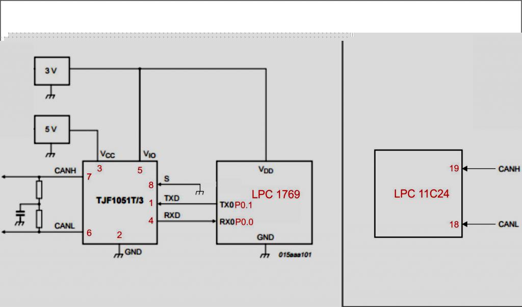
I have used TJF1051T/3 transceiver with connections shown in attached image.
I think CAN1 connections are good.
As I mentioned previously I am using "periph_can" example and board library provided by LPC. Downloaded from link:
https://www.lpcware.com/content/nxpfile/lpcopen-software-development-platform-lpc17xx-packages
I assume muxing in this library is already set, Or do I need to change any thing in this library to use CAN1?
Thanks,
KBalar
Hi,
I have used TJF1051T/3 transceiver with connections shown in attached image.
I think CAN1 connections are good.
As I mentioned previously I am using "periph_can" example and board library provided by LPC. Downloaded from link:
https://www.lpcware.com/content/nxpfile/lpcopen-software-development-platform-lpc17xx-packages
I assume muxing in this library is already set, Or do I need to change any thing in this library to use CAN1?
Thanks,
KBalar
06-15-2016
01:15 PM
1,049 Views
NXP Employee
- Mark as New
- Bookmark
- Subscribe
- Mute
- Subscribe to RSS Feed
- Permalink
- Report Inappropriate Content
Content originally posted in LPCWare by R2D2 on Mon Sep 28 13:08:30 MST 2015
Quote: balarkalpesh@gmail.com
What could be wrong in this?
:quest:
You're kidding :quest:
Obviously you CAN1 setup is wrong (or your transceiver connection)...
Your code snippet isn't showing how you setup CAN1 and you don't describe what you have connected :~
So I have to guess: Pin Muxing in your board library is wrong...