
- NXP Forums
- Product Forums
- General Purpose MicrocontrollersGeneral Purpose Microcontrollers
- i.MX Forumsi.MX Forums
- QorIQ Processing PlatformsQorIQ Processing Platforms
- Identification and SecurityIdentification and Security
- Power ManagementPower Management
- MCX Microcontrollers
- S32G
- S32K
- S32V
- MPC5xxx
- Other NXP Products
- Wireless Connectivity
- S12 / MagniV Microcontrollers
- Powertrain and Electrification Analog Drivers
- Sensors
- Vybrid Processors
- Digital Signal Controllers
- 8-bit Microcontrollers
- ColdFire/68K Microcontrollers and Processors
- PowerQUICC Processors
- OSBDM and TBDML
-
- Solution Forums
- Software Forums
- MCUXpresso Software and ToolsMCUXpresso Software and Tools
- CodeWarriorCodeWarrior
- MQX Software SolutionsMQX Software Solutions
- Model-Based Design Toolbox (MBDT)Model-Based Design Toolbox (MBDT)
- FreeMASTER
- eIQ Machine Learning Software
- Embedded Software and Tools Clinic
- S32 SDK
- S32 Design Studio
- Vigiles
- GUI Guider
- Zephyr Project
- Voice Technology
- Application Software Packs
- Secure Provisioning SDK (SPSDK)
- Processor Expert Software
-
- Topics
- Mobile Robotics - Drones and RoversMobile Robotics - Drones and Rovers
- NXP Training ContentNXP Training Content
- University ProgramsUniversity Programs
- Rapid IoT
- NXP Designs
- SafeAssure-Community
- OSS Security & Maintenance
- Using Our Community
-
- Cloud Lab Forums
-
- Home
- :
- Product Forums
- :
- 8-bit Microcontrollers
- :
- JM60 SCI INIT RS232
JM60 SCI INIT RS232
- Subscribe to RSS Feed
- Mark Topic as New
- Mark Topic as Read
- Float this Topic for Current User
- Bookmark
- Subscribe
- Mute
- Printer Friendly Page
JM60 SCI INIT RS232
- Mark as New
- Bookmark
- Subscribe
- Mute
- Subscribe to RSS Feed
- Permalink
- Report Inappropriate Content
Hello all,
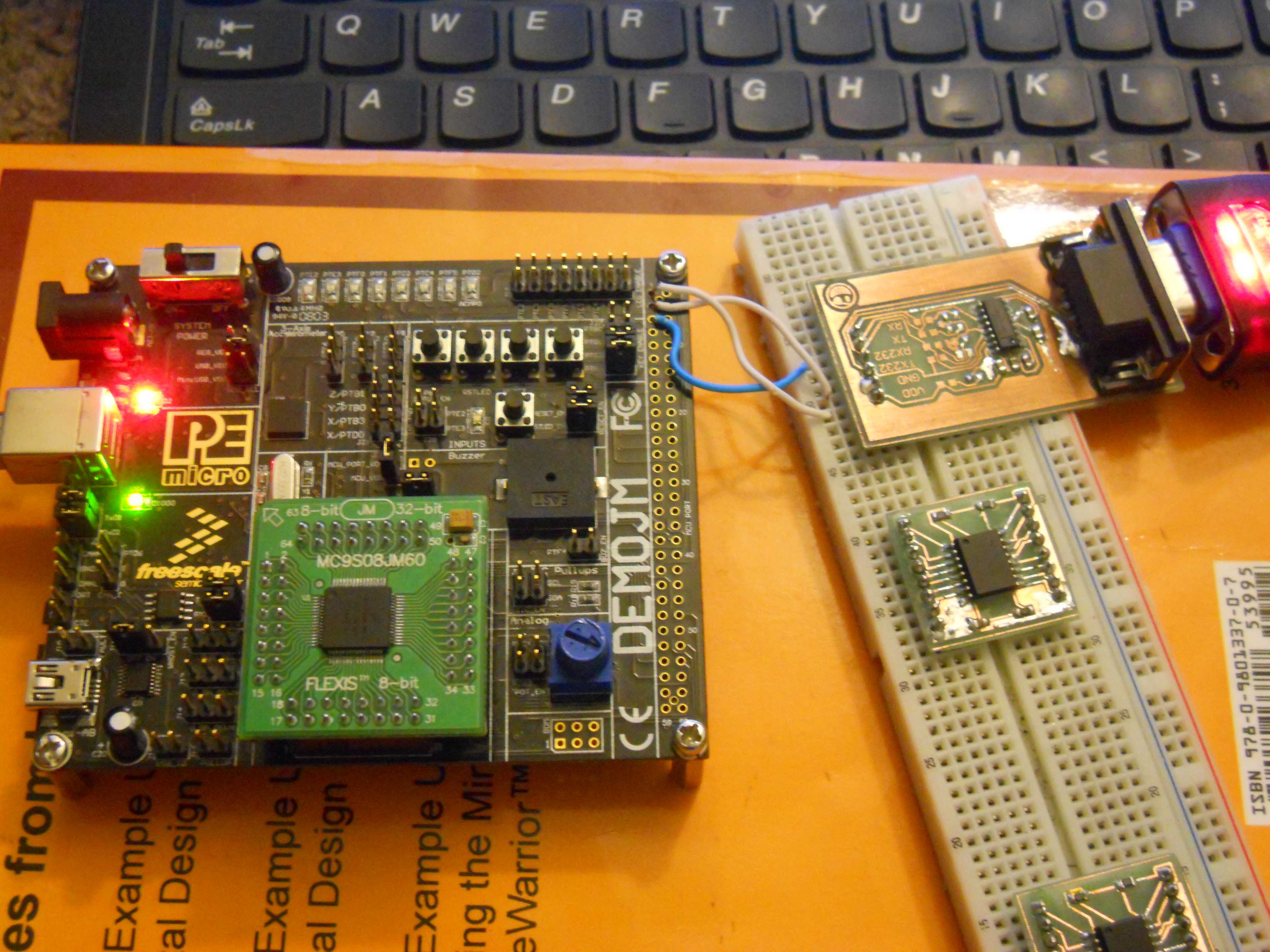
I have recently started programming hcs08 micro controllers At the moment I am learning using a DEMOJM board. I want to initialize the SCI module on the JM60 chip. This is what I have written so far:
#include <hidef.h> /* common defines and macros */ #include "derivative.h" /* derivative-specific definitions */ #include "hcs08.h" void SerTx0(unsigned char); void SCI1_OutString(char *pt); void MSDelay(unsigned int); void main(void) { SOPT1 = bBKGDPE; SCI1BDH=0x00; SCI1BDL=26; //8MHz/2=4MHz, 4MHz/16=250,000 and 250,000/9600=26 SCI1C1=0x00; SCI1C2=0x0C; for(;;){ SCI1_OutString("a"); } } void SerTx0(unsigned char c) //SCI0 (COM0 of HC08 chip) { while(!(SCI1S1 & 0x80)); //make sure the last bit is gone SCI1D=c; //before giving it another byte } // Function for writing a string into the sci tx buffer void SCI1_OutString(char *pt) { while(*pt) { SerTx0(*pt); pt++; } } void MSDelay(unsigned int itime) //msec delay { unsigned int i; unsigned int j; for(i=0;i<itime;i++) for(j=0;j<4000;j++); }
I also built my own RS232 board to interface with the chip. Check out the pictures.
The problem is I am getting alot of garbage out of my Tx line on my terminal screen which makes me think I have set up my baud rate incorrectly on my code.
I also though my board was wired incorrectly but once I connect it to a HCS12 chip and Parallax Propeller chip the Tx and Rx lines output the correct strings and characters.
Could someone lend me a hand and tell me what I have initialized incorrectly. I will really appreciate it
- Mark as New
- Bookmark
- Subscribe
- Mute
- Subscribe to RSS Feed
- Permalink
- Report Inappropriate Content
Let me try using the default 16Mhz bus clock to see if I can get the correct Tx output.
This means that I will set the following in my code:
SCI1BDL=52; //16MHz/2=8MHz, 4MHz/16=500 kilohertz and 500,000/9600=52
and it works! awsome.
I had originally wrote my code for a mc9s08gb60a chip with a 4MHz crystal. Correct me if I am wrong but does the mc9s08gb60a have a 8Mhz clock?
- Mark as New
- Bookmark
- Subscribe
- Mute
- Subscribe to RSS Feed
- Permalink
- Report Inappropriate Content
Kelly, the baud rate configuration doesn't seem to be a problem, you've calculated for 4 MHz, and you're getting about 9615 bps, which is a 0.15% error, far below the maximum error of 4%. My guess is your bus clock isn't actually doing 4 MHz. If you're not doing any clock initialization at all the default clock is the FLL output (from the MCG module) running from the internal 32 kHz clock. But also notice something, the "32 kHz" clock is actually trimmable, it can be changed a little bit, from 31.25 to 39.0625 kHz per the electrical specs of the JM60 (table A-12 of the data sheet). The default trim out of factory is 31.25 kHz. The default config out of reset for the JM60 is FLL multiplies that signal by 1024 and then divides down by 2, in other words: 16 MHz.
So you have two options, if you want to keep the 16 MHz bus clock, recalculate your baud rate divider based on 16 MHz. If you still want a 4 MHz bus clock go ahead and configure bits BDIV from register MCGC2 to a value of 3 so that the output from the FLL is divided down by 8.
- Mark as New
- Bookmark
- Subscribe
- Mute
- Subscribe to RSS Feed
- Permalink
- Report Inappropriate Content
Sorry, made a blooper, the default frequency out of reset is 8 MHz, there's a fixed divide by 2 after the clock output. So you have to use BDIV to divide by 4, not by 8 as I previously stated.