
- NXP Forums
- Product Forums
- General Purpose MicrocontrollersGeneral Purpose Microcontrollers
- i.MX Forumsi.MX Forums
- QorIQ Processing PlatformsQorIQ Processing Platforms
- Identification and SecurityIdentification and Security
- Power ManagementPower Management
- MCX Microcontrollers
- S32G
- S32K
- S32V
- MPC5xxx
- Other NXP Products
- Wireless Connectivity
- S12 / MagniV Microcontrollers
- Powertrain and Electrification Analog Drivers
- Sensors
- Vybrid Processors
- Digital Signal Controllers
- 8-bit Microcontrollers
- ColdFire/68K Microcontrollers and Processors
- PowerQUICC Processors
- OSBDM and TBDML
-
- Solution Forums
- Software Forums
- MCUXpresso Software and ToolsMCUXpresso Software and Tools
- CodeWarriorCodeWarrior
- MQX Software SolutionsMQX Software Solutions
- Model-Based Design Toolbox (MBDT)Model-Based Design Toolbox (MBDT)
- FreeMASTER
- eIQ Machine Learning Software
- Embedded Software and Tools Clinic
- S32 SDK
- S32 Design Studio
- Vigiles
- GUI Guider
- Zephyr Project
- Voice Technology
- Application Software Packs
- Secure Provisioning SDK (SPSDK)
- Processor Expert Software
-
- Topics
- Mobile Robotics - Drones and RoversMobile Robotics - Drones and Rovers
- NXP Training ContentNXP Training Content
- University ProgramsUniversity Programs
- Rapid IoT
- NXP Designs
- SafeAssure-Community
- OSS Security & Maintenance
- Using Our Community
-
-
- Home
- :
- i.MX Forums
- :
- i.MX RT
- :
- Re: ROM bootloader behavior while reading status register and execute configuration commands
ROM bootloader behavior while reading status register and execute configuration commands
- Subscribe to RSS Feed
- Mark Topic as New
- Mark Topic as Read
- Float this Topic for Current User
- Bookmark
- Subscribe
- Mute
- Printer Friendly Page
- Mark as New
- Bookmark
- Subscribe
- Mute
- Subscribe to RSS Feed
- Permalink
- Report Inappropriate Content
We are setting up the boot configuration for a serial NOR flash (IS25LP128) to work with i.MX-RT1051B
While checking our boot configuration with the oscilloscope we encountered, that the i.MX-RT1051B processor always clocks 4 data byte out. According our configuration the read status LUT sequence would only ask for 1 byte.
Our boot configuration code snipped is attached, also captured SPI signal (CE#; C2/Z2, CLK; C1/Z1, SI; C4/Z4, SO; C3/Z3) with oscilloscope.
We would like to understand:
- Why does reading status register clocks 4 data byte out?
- Is there any differences (e.g. which is executed first or only on power-up, HW reset, ...) between device mode configuration and config command, which are both part of FlexSPI boot configuration?
- Is the ROM bootloader using a fix LUT sequence for status register reading or the configured entries in boot configuration?
For any helpful explanation / answer many thanks.
Best regards
Leopold
Solved! Go to Solution.
- Mark as New
- Bookmark
- Subscribe
- Mute
- Subscribe to RSS Feed
- Permalink
- Report Inappropriate Content
Hi,
Thanks for your reply.
1) Can you please confirm, that the ROM bootloader of i.MX-RT1051B is clocking out 4 data bytes in case the status register is read?
-- Yes, in further, I tried to use lpspi_interrupt_b2b_master demo to send the READ STATUS REGISTER command (0x05) to the QSPI flash: IS25WP064A and I replicated the phenomenon.
After the IS25WP064A receive the READ STATUS REGISTER command (0x05), the QSPI flash will keep sending back the value of read status register regardless of any next data that the MCU transfers.
So I think it's definitely related to the QSPI itself.

Have a great day,
TIC
-------------------------------------------------------------------------------
Note:
- If this post answers your question, please click the "Mark Correct" button. Thank you!
- We are following threads for 7 weeks after the last post, later replies are ignored
Please open a new thread and refer to the closed one, if you have a related question at a later point in time.
-------------------------------------------------------------------------------
- Mark as New
- Bookmark
- Subscribe
- Mute
- Subscribe to RSS Feed
- Permalink
- Report Inappropriate Content
Dear TIC,
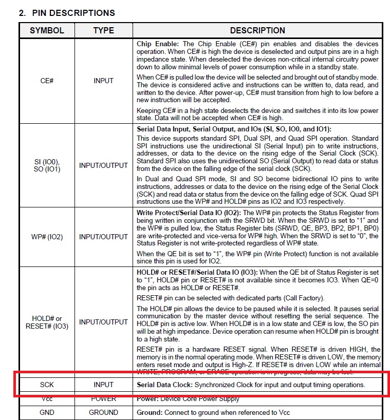
you may also have read the datasheet of IS25LP128 NOR flash chip. I have added the pin description table of it and it clearly states that the SCK is an input signal for IS25LP128 NOR flash chip. Nothing else I would have expect, since the i.MX-RT1051B is the master on SPI and the only one which drives (waves) the SCK.
Therefore I ask again, can you please confirm, that the ROM bootloader of i.MX-RT1051B is clocking out 4 data bytes in case the status register is read?
Best regards
Leopold
- Mark as New
- Bookmark
- Subscribe
- Mute
- Subscribe to RSS Feed
- Permalink
- Report Inappropriate Content
Hi,
Thank you for your interest in NXP Semiconductor products and for the opportunity to serve you.
1) Why does the reading status register clocks 4 data byte out?
-- To be honest, I don't know, the phenomenon is definitely inconsistent with the datasheet for IS25LP128. I think it needs to contact ISSI for confirming.

2) Is there any differences (e.g. which is executed first or only on power-up, HW reset, ...) between device mode configuration and config command, which are both parts of FlexSPI boot configuration?
-- No, I'm afraid not.
3) Is the ROM bootloader using a fixed LUT sequence for status register reading or the configured entries in boot configuration?
-- I think we use a fixed LUT sequence for status register reading even I don't know the source code of the ROM code.
Have a great day,
TIC
-------------------------------------------------------------------------------
Note:
- If this post answers your question, please click the "Mark Correct" button. Thank you!
- We are following threads for 7 weeks after the last post, later replies are ignored
Please open a new thread and refer to the closed one, if you have a related question at a later point in time.
-------------------------------------------------------------------------------
- Mark as New
- Bookmark
- Subscribe
- Mute
- Subscribe to RSS Feed
- Permalink
- Report Inappropriate Content
Dear TIC,
many thanks for your answer. But regarding 1) I expect NXP should give the answer.
Why we have to contact ISSI? The i.MX-RT1051B is master on FlexSPI and driving the SCK.
Best regards
Leopold
- Mark as New
- Bookmark
- Subscribe
- Mute
- Subscribe to RSS Feed
- Permalink
- Report Inappropriate Content
Hi,
Thanks for your reply.
1) Can you please confirm, that the ROM bootloader of i.MX-RT1051B is clocking out 4 data bytes in case the status register is read?
-- Yes, in further, I tried to use lpspi_interrupt_b2b_master demo to send the READ STATUS REGISTER command (0x05) to the QSPI flash: IS25WP064A and I replicated the phenomenon.
After the IS25WP064A receive the READ STATUS REGISTER command (0x05), the QSPI flash will keep sending back the value of read status register regardless of any next data that the MCU transfers.
So I think it's definitely related to the QSPI itself.
Have a great day,
TIC
-------------------------------------------------------------------------------
Note:
- If this post answers your question, please click the "Mark Correct" button. Thank you!
- We are following threads for 7 weeks after the last post, later replies are ignored
Please open a new thread and refer to the closed one, if you have a related question at a later point in time.
-------------------------------------------------------------------------------
- Mark as New
- Bookmark
- Subscribe
- Mute
- Subscribe to RSS Feed
- Permalink
- Report Inappropriate Content
Hi,
Thanks for your reply.
According to your attachment, the ROM code execute the Read Status Register (RDSR) instruction and the SPI wave is as same as the IS25LP128's datasheet demonstrates except for that returning 4 bytes instead of 1 byte, in my opinion, it seems to be related to specific of the flash chip.
In further, you can try to confirm that by using the SPI interface to send the Read Status Register command (05h) to contact the IS25LP12.
Meanwhile, the expert of ISSI also can share comments about the phenomenon, then help us figure it out.
Have a great day,
TIC
-------------------------------------------------------------------------------
Note:
- If this post answers your question, please click the "Mark Correct" button. Thank you!
- We are following threads for 7 weeks after the last post, later replies are ignored
Please open a new thread and refer to the closed one, if you have a related question at a later point in time.
-------------------------------------------------------------------------------