
- NXP Forums
- Product Forums
- General Purpose MicrocontrollersGeneral Purpose Microcontrollers
- i.MX Forumsi.MX Forums
- QorIQ Processing PlatformsQorIQ Processing Platforms
- Identification and SecurityIdentification and Security
- Power ManagementPower Management
- MCX Microcontrollers
- S32G
- S32K
- S32V
- MPC5xxx
- Other NXP Products
- Wireless Connectivity
- S12 / MagniV Microcontrollers
- Powertrain and Electrification Analog Drivers
- Sensors
- Vybrid Processors
- Digital Signal Controllers
- 8-bit Microcontrollers
- ColdFire/68K Microcontrollers and Processors
- PowerQUICC Processors
- OSBDM and TBDML
-
- Solution Forums
- Software Forums
- MCUXpresso Software and ToolsMCUXpresso Software and Tools
- CodeWarriorCodeWarrior
- MQX Software SolutionsMQX Software Solutions
- Model-Based Design Toolbox (MBDT)Model-Based Design Toolbox (MBDT)
- FreeMASTER
- eIQ Machine Learning Software
- Embedded Software and Tools Clinic
- S32 SDK
- S32 Design Studio
- Vigiles
- GUI Guider
- Zephyr Project
- Voice Technology
- Application Software Packs
- Secure Provisioning SDK (SPSDK)
- Processor Expert Software
-
- Topics
- Mobile Robotics - Drones and RoversMobile Robotics - Drones and Rovers
- NXP Training ContentNXP Training Content
- University ProgramsUniversity Programs
- Rapid IoT
- NXP Designs
- SafeAssure-Community
- OSS Security & Maintenance
- Using Our Community
-
-
- Home
- :
- i.MX Forums
- :
- i.MX Processors
- :
- Re: IMX6 Solo intermittent boot-up failures
IMX6 Solo intermittent boot-up failures
- Subscribe to RSS Feed
- Mark Topic as New
- Mark Topic as Read
- Float this Topic for Current User
- Bookmark
- Subscribe
- Mute
- Printer Friendly Page
IMX6 Solo intermittent boot-up failures
- Mark as New
- Bookmark
- Subscribe
- Mute
- Subscribe to RSS Feed
- Permalink
- Report Inappropriate Content
BACKGROUND:
We have an existing system (custom designed), that exhibits a bootup failure. The nature of the failure is that the processor appears to not recognize our boot device properly on first time power up, even though our BOOT_MODE and Configuration pins are set properly.
Some notes:
- When bootup fails, we notice immediate activity on USB. We believe this indicates that the wrong boot source has been latched. Our system is designed to boot from an eMMC card, but it seems to move immediately to USB boot.
- With power on, executing a POR_B causes a proper boot every time. SO we surmise the issue has to do with power sequencing or some other power on anomaly.
SOLUTION 1: Change from ANA_V2P5V to VSNVS for all boot config pullups (much earlier in sequence and away from strange ON-OFF-ON behavior as exhibited in the following figures)
(See Figure 1): ON-OFF-ON LDOs. Our Config Pins appear to pull up during this transition. Boot fails

(See Figure 2): Moved Config Pins to Much early in Boot (VSNVS) out of the ON-OFF-ON Area. Boots reliably

(See Figure 3): Capture showing that the VDDSOC/ARM_CAP ON-OFF-ON is internal, not a result of VDDSOC/ARM_IN.

Notes for Figures 1 - 3:
- Documentation implies the boot config is latched at rising edge of POR_B (i.MX6Dual/6Quad Applications Processor Reference Manual Rev 2, 06/2014)
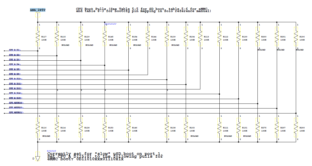
- Currently boot resistors are strapped to ANA_V2PV which is safely stable before POR_B rising edge
- When we change config resistors to VSNVS rail (80ms earlier than ANA_2P5V) we boot reliably
- This seems to behave as if the boot config is being read/latched at this unstable VDDSOC ON/OFF/ON area
USB ACTIVITY: On Our failure boot-up case, we see USB_OTG doing something early BEFORE POR_B. eMMC never executes. If, with power still applied, you perform a second POR_B, then boot from eMMC always happens correctly
(See Figure 4): USB Activity before POR_B failure

(See Figure 5): Proper Boot with eMMC and USB activity as expected

Power-up rails/POR_B sequence:
(See Figure 6): Power-up sequence/POR_B

Fix #2 = We have found that reducing the capacitor on VDDSOC_CAP from 22uF to 10uF to 0uF seems to positively impact the boot (NOTE: A recent test showed one failure with a 10uF capacitor, so this is not seen as reliable). The VDDSOC_CAP signal appears to be the one that contributes to the issue (not VDDARM_CAP).We have tested with 22uF/10uF/0uF on the VDD
(See Figure 7 - VDDSOC_CAP with 22uF Cap Fails)

(See Figure 8 - VDDSOC_CAP with 10uF Cap normally boots, but has failed at least once)

(See Figure 9 - VDDSOC_CAP with 0uF Cap boots reliably)

NOTE: We are fully aware that the MAX capacitor value is 22uF including trace capacitance and have improved our design to be as close as mechanically possible to the _CAP pins. However, even with a 10uF + small trace length we are not booting reliably so we are not convinced this is all of the problem and do not feel this explains the strange on-off-on behavior.
Fix#3 = Burn eFUSES resolves intermittent boot
This will be done, but it does not solve our first time boot problem. And we also do not understand why the boot fuse method would not be effected in the same way as the config pins. We know Freescale recommends using the boot fuses in their documentation. We need to understand WHY this is more reliable.
Answers needed from Freescale:
Q1) What would cause the VDDSOC and VDDARM LDOs to exhibit the ON-OFF-ON at power-up? Is this a known issue or errata?
Q2) Is the ON-OFF-ON situation somehow causing the apparent early latching? And how do we mitigate it in such a way that we guarantee a reliable boot from the config pins?
Q3) Why does moving the config pins to a rail that powers up much earlier help the situation?
Q4) What is different about the latching of the configuration when using the eFUSES versus the pull-ups/pull-downs that it would not suffer the same problem?
In general, our goal is to fully understand the mechanism that is causing this boot failure inside the chip so that we can reliably implement our fix and KNOW that it is going to work.
- Mark as New
- Bookmark
- Subscribe
- Mute
- Subscribe to RSS Feed
- Permalink
- Report Inappropriate Content
##what PMIC are you using, in attached diagram VDDARM_IN,VDDSOC_IN
##provided simultaneously, thus huge current soike may occur -
##this may be reason for "turning ON-OFF-ON".
##For i.MX6SDL usually MMPF0100 "F0" is used, it gives powering
##VDDARM_IN,VDDSOC_IN in different time steps.
We installed new programmed PMIC with staggered ARM/SOC on time, "F0":
VDD_ARM on 1ms before VDD_SOC
same result, same boot failure
NOTE: VDDARM_CAP and VDD_SOC still ON/OFF/ON same time (no 1ms stagger) somthing inside IMX still produce simultaneous VDDARM_CAP and VDDSOC_CAP ON/OFF/ON.
- Mark as New
- Bookmark
- Subscribe
- Mute
- Subscribe to RSS Feed
- Permalink
- Report Inappropriate Content
so you can not attach jtag and check SBMR1,2
registers even with 24MHz working, correct ?
Do you see any activity on eMMC, does it tries to read from
SD port or processor immediately goes to Serial Downloader mode ?
How many boards have such behaviour: one, all ?
- Mark as New
- Bookmark
- Subscribe
- Mute
- Subscribe to RSS Feed
- Permalink
- Report Inappropriate Content
FAILURE Case where board does not boot:
mem read 0x20D8004 (SBMR1)
0x40000000
mem read 0x20D801C (SBMR2)
0x22000001
WORKING Case where board does boot:
mem read 0x20D8004 (SBMR1)
0x40005062
mem read 0x20D801C (SBMR2)
0x22000001
This seems to confrim our suspicion that the boot config resistors were getting latched wrongly at the unexplainable ON/OFF/ON internal IMX rails. And they are not getting re-latched at the good POR_B deassert which is much later in time when the supplies are all stable.
- Mark as New
- Bookmark
- Subscribe
- Mute
- Subscribe to RSS Feed
- Permalink
- Report Inappropriate Content
how connected boot pins, what resistor values are used,
is smth else connected to EIM_DA8-15 pins (parallel NOR for example ?)
when you are saying :
"Change from ANA_V2P5V to VSNVS for all boot config pullups"
what pins do you mean by "all boot config pullups" , only BOOT_MODE0,1 ?
boot pins EIM_DA15-8 BOOT_CFG2[7:0], EIM_DA7-0 BOOT_CFG1[7:0]
have power domain NVCC_EIM, they are not latched correctly according to
your SBMR1 reading 0x40000000 vs 0x40005062
could you check NVCC_EIM power rail by oscilloscope and signals
at these boot pins (EIM_DA0-15) as close to processor as possible.
Additionally please check processor 24MHz and 32 KHz clock - are they stable
and good shape ?
Also is some externally powered device can be connected to board when you
powers board first time ? May be board connected to PC with
UART or USB, HDMI monitor, SATA HDD, camera ? Could you
disconnect all and check ? If there is additional case "ground", remove it.
- Mark as New
- Bookmark
- Subscribe
- Mute
- Subscribe to RSS Feed
- Permalink
- Report Inappropriate Content
##"Change from ANA_V2P5V to VSNVS for all boot config pullups"
##what pins do you mean by "all boot config pullups" , only BOOT_MODE0,1 ?
BOOT_MOCE[1:0] are pulled up to VSNVS (stable 93ms before POR_B de-assert)
BOOT_CONFIGX pins are pulled up the ANA_2P5V (stable 14ms before POR_B de-assert)
(because this was better for PCB layout and Freescale documentation states these boot config I/O values are latched at POR_B de-assert)
##boot pins EIM_DA15-8 BOOT_CFG2[7:0], EIM_DA7-0 BOOT_CFG1[7:0]
##have power domain NVCC_EIM, they are not latched correctly according to
##your SBMR1 reading 0x40000000 vs 0x40005062
CORRECT, can Freescale expalin why boot config I/O is llatching at ON/OFF/ON VDDSOC_CAP glitch and not correctly latching at POR_B de-assert which is safely when power supplies are stable?
##could you check NVCC_EIM power rail by oscilloscope and signals
##at these boot pins (EIM_DA0-15) as close to processor as possible.
##Additionally please check processor 24MHz and 32 KHz clock - are they stable
##and good shape ?
NVCC_EIM = ANA_2P5V looks lie very clean scope capture. As shown in timing diagram, this rails happens to comeup about same time as ON/OFF/ON glitch problem area. Does Freescale know what is causing this ON/OFF/ON on the VDDSOC_CAP and VDDARM_CAP rails?
I have previously confrimed by scope captures 24MHz and 32KHz clock look good.
##Also is some externally powered device can be connected to board when you
##powers board first time ? May be board connected to PC with
##UART or USB, HDMI monitor, SATA HDD, camera ? Could you
##disconnect all and check ? If there is additional case "ground", remove it.
NO, no external devices or cables etc are connected to IMX ports at intermittent boot failure.
- Mark as New
- Bookmark
- Subscribe
- Mute
- Subscribe to RSS Feed
- Permalink
- Report Inappropriate Content
I elevated this issue internally (SR-1-3603186388)
hope it will be resolved soon.
Best regards
igor
- Mark as New
- Bookmark
- Subscribe
- Mute
- Subscribe to RSS Feed
- Permalink
- Report Inappropriate Content
Thank you Igor!
How can I track progress of SR-1-3603186388?
Regards,
Shawn
- Mark as New
- Bookmark
- Subscribe
- Mute
- Subscribe to RSS Feed
- Permalink
- Report Inappropriate Content
Hi Shawn
below answer from expert:
---------------------------------------------
It seems the boot fail is caused by the RTC issue ERR007926, the device will switch to USB download mode wwhen boot up fail.
Please check below items
- Extend the POR_B release time (around 1 second)
- Measure the Data/Clk signal on boot device (to check the boot mode latch is correct)
The VDDSOC_CAP On-Off-On seems cause by the VDDHIGH_CAP turn on time.
Please compare the VDDSOC_CAP with VDDHIGH_CAP.
--------------------------------------------
Best regards
igor
- Mark as New
- Bookmark
- Subscribe
- Mute
- Subscribe to RSS Feed
- Permalink
- Report Inappropriate Content
##It seems the boot fail is caused by the RTC issue ERR007926, the device will switch to USB download mode wwhen boot up fail.
##Please check below items
##- Extend the POR_B release time (around 1 second)
We have already tried this test, using external POR_B we deasserted POR_B ~5seconds which did not cause successful boot, 2nd POR_B at ~10 seconds resulted in successful boot. We cannot do >1sec POR_B with our present PMIC design, and we cannot implement double POR_B with current PMIC design.
##- Measure the Data/Clk signal on boot device (to check the boot mode latch is correct)
1st POR_B we attempted to boot USB, 2nd POR_B we booted correctly from eMMC
##The VDDSOC_CAP On-Off-On seems cause by the VDDHIGH_CAP turn on time.
##Please compare the VDDSOC_CAP with VDDHIGH_CAP
Not clear on this comment, are you asking us to change VDDHIGH_CAP input timing to be before or after VDDSOC/VDDARM inputs?
- Mark as New
- Bookmark
- Subscribe
- Mute
- Subscribe to RSS Feed
- Permalink
- Report Inappropriate Content
update from expert:
--------------------------------------------------
The Power up sequence (on external page) seems OK.
Can you ask customer to provide the XTAL related circuit and do one more test to clarify the problem?
- Use internal ring oscillator with normal boot sequence (please short RTC_XTALI pin to GND
--------------------------------------------------
~igor
- Mark as New
- Bookmark
- Subscribe
- Mute
- Subscribe to RSS Feed
- Permalink
- Report Inappropriate Content
Short RTC_XTALI (Y3-pin1) to gnd, same result, 1st boot-up HANGS, manual 2nd POR_B boots successfully.

- Mark as New
- Bookmark
- Subscribe
- Mute
- Subscribe to RSS Feed
- Permalink
- Report Inappropriate Content
Hi Shawn
below feedback from expert
----------------------------------------------------
Since use internal ring oscillator test result shows the 1st time boot fail still exist (prove
it is not RTC issue) and the eFuse boot can solve it (Fix #3 in your report), so I assume
the issue is caused by the GPIO Boot configure pins latch problem.
Can you help to clarify below questions:
- What’s the supply voltage for MX6S NVCC_EIM?
- What’s the GPIO Boot configure pins pull up resistor value?
- Is the ANA2P5V supply to the pull up resistors directly? Or through buffer?
(Please provide the related schematic if the ANA2P5V supply to the pull up resistors through buffer)
Please note there are 100K pull-down resistors for boot config pins (Before reset state).
So, If the supply voltage for NVCC_EIM is 3.3V (MISC_3.3V) and use 10K resistor pull up to 2.5V, the voltage value on the boot config pins will be
(2.5V / (100K+10K)) * 100K = 2.2727V
It is lower than VIL (3.3V*0.7 = 2.31V) and may cause pin value latch error problem.
----------------------------------------------------
regarding schematic you can ask FAEs post it to secure internal forum:
IMX6 Solo intermittent boot-up failures
Best regards
igor
- Mark as New
- Bookmark
- Subscribe
- Mute
- Subscribe to RSS Feed
- Permalink
- Report Inappropriate Content
Can you help to clarify below questions:
##•What’s the supply voltage for MX6S NVCC_EIM?
2.5V
##•What’s the GPIO Boot configure pins pull up resistor value?
100K
##•Is the ANA2P5V supply to the pull up resistors directly? Or through buffer?
DIRECTLY, NO BUFFERS
## (Please provide the related schematic if the ANA2P5V supply to the pull up resistors through buffer)
##Please note there are 100K pull-down resistors for boot config pins (Before reset state).
##So, If the supply voltage for NVCC_EIM is 3.3V (MISC_3.3V) and use 10K resistor pull up to 2.5V, the voltage value on the boot config pins will be
##(2.5V / (100K+10K)) * 100K = 2.2727V
##It is lower than VIL (3.3V*0.7 = 2.31V) and may cause pin value latch error problem.
ANA_2P5 is stable 14ms before POR_B release, At POR_B release all voltages are stable,
We don't see any problem with boot pull-up condition at 1st POR_B release (de-assert)
----------------------------------------------------
##regarding schematic you can ask FAEs post it to secure internal forum:
- Mark as New
- Bookmark
- Subscribe
- Mute
- Subscribe to RSS Feed
- Permalink
- Report Inappropriate Content
Hi Shawn
below feedback from expert
--------------------------------------------------------
As you know, the boot configures latched when the rising edge of POR_B release.
Since they are using 100K pull up and there has internal 100K pull down, so the voltage value of "H" pins are 1.25V before POR_B release.
The 1.25V is lower than VIL (since NVCC_EIM supply voltage is 2.5V, so VIL= 2.5V *0.7 = 1.775V) and may cause boot configure pins latch problem.
Suggest use 10K to instead the 100K pull up resistors for boot configure pins.
I can’t answer why reduce the VDDSOC_CAP bulk cap value can makes the boot success in this case. Ideally the boot fail is caused by the wrong voltage level of boot configure pins, not power up sequence of VDDSOC_CAP. And in our experience, the 22uF bulk cap is necessary and reduce the cap value (or bad placement) will cause system unstable. Please reference to the MX6 HW development guide for the detail.
-------------------------------------------------------
Best regards
igor
- Mark as New
- Bookmark
- Subscribe
- Mute
- Subscribe to RSS Feed
- Permalink
- Report Inappropriate Content
Hello igor,
One of the first things we tried was changing 100K pull-ups to harder 4.7K having suspiscion that they were too week. The result was the same, 1st POR_B release fails to boot, re-assert POR_B 2nd POR_B release boots from eMMC correctly always.
We still feel something inside the chip is latching at that power-up ON/OFF/ON VDDSOC_CAP area and does not unlatch until POR_B goes L/H again.
- Mark as New
- Bookmark
- Subscribe
- Mute
- Subscribe to RSS Feed
- Permalink
- Report Inappropriate Content
I had a similar experience with the first board I developed as what is described in this thread. I ended up changing the BOOT_MODE[1:0] pullups to 10k ohm for bit 1 and 10k ohm pulldown for 0 to force booting from gpio overrides. This resolved the similar boot sequencing. The BOOT_MODE and CFG lines are capable of being pulled up to SNVS only from the MMPF0100 on my design as well. Any other supplies would possibly be out of order per the references.
As a note, I had to adjust the TAMPER pin as well even though I don't directly use the feature.
Just wanted to share a similar experience that was resolved on my custom board,
John
- Mark as New
- Bookmark
- Subscribe
- Mute
- Subscribe to RSS Feed
- Permalink
- Report Inappropriate Content
Thanks John,
We already are similar to that.
BOOT_MODE[1] = 10K pull-up to VSNVS
BOOT_MODE[0] = 10K pull-down
FYI, Our VSNVS is stable 93mS before POR_B release and 75 ms before the unexplained VDDSOC_CAP ON/OFF/ON.
- Mark as New
- Bookmark
- Subscribe
- Mute
- Subscribe to RSS Feed
- Permalink
- Report Inappropriate Content
Hi Shawn
below feedback from expert
-----------------------------------------
Can you ask customer to change the power up sequence?
I want use same power supply ( or sequence) to supply the VDD_SNVS_IN and VDDHIGH_IN, and the power up sequence will be
VDD_SNVS_IN (with VDDHIGH_IN) -> VDDARM_IN (with VDDSOC_IN) -> others
Ideally, this power up sequence can prevent the ON-OFF-ON in VDDSOC_CAP (and VDDARM_CAP).
Ps. 1. Please make sure the pull up resistors value are 10K (or lower)
2. Please confirm the power supply for VDD_SNVS_IN (and VDDHIGH_IN) output current is enough (125mA or above)
-----------------------------------------
~igor
- Mark as New
- Bookmark
- Subscribe
- Mute
- Subscribe to RSS Feed
- Permalink
- Report Inappropriate Content
This is a difficult modification for us to make right now. Can you provide more details about how/why this will eliminate the ON-OFF-ON VCCSOC_CAP problem?
- Mark as New
- Bookmark
- Subscribe
- Mute
- Subscribe to RSS Feed
- Permalink
- Report Inappropriate Content
Answer from expert:
----------------------------------------------
For the VDD_xxx_CAP ON OFF ON sequence
- The regulation control loop is powered by VDDHIGH_IN.
- As the VDDHIGH_IN voltage ramps, while the VDDXXX_IN voltages are present, a point exists where the regulation FETS are briefly turned fully on.
- This causes the VDDXXX_CAP pins to equal the VDDXXX_IN pins.
- As the VDDHIGH_IN voltage increases, this momentary condition is resolved and the VDDXXX_CAP voltage decays with leakage until such time that the chip is ready to normally power up the VDDXXX_CAP pins.
- This startup phenomenon does not impact the LDO regulation or functionality in the application.
But it only can explain the VDD_xxx_CAP ON OFF ON sequence, not 1st boot fail problem.
--------------------------------------------
~igor
- Mark as New
- Bookmark
- Subscribe
- Mute
- Subscribe to RSS Feed
- Permalink
- Report Inappropriate Content
Can we ever get to root cause of issue where first POR_B deassertion after all power rails stable and eMMC boot never executes and we fail to USB OTG boot, BUT re-assert POR_B and 2nd POR_B deassertion ALWAYS boot eMMC correctly? This situation must be internal to the chip, there is no difference to the power rails or the boot config pull-ups pull downs between the 1st POR_B deassertion and the 2nd POR_B deassertion. We are expecting an explanation about what internally to the chip might explain this situation.