
- Forums
- Product Forums
- General Purpose MicrocontrollersGeneral Purpose Microcontrollers
- i.MX Forumsi.MX Forums
- QorIQ Processing PlatformsQorIQ Processing Platforms
- Identification and SecurityIdentification and Security
- Power ManagementPower Management
- Wireless ConnectivityWireless Connectivity
- RFID / NFCRFID / NFC
- Advanced AnalogAdvanced Analog
- Neural Processing UnitsNeural Processing Units
- MCX Microcontrollers
- S32G
- S32K
- S32V
- MPC5xxx
- Other NXP Products
- S12 / MagniV Microcontrollers
- Powertrain and Electrification Analog Drivers
- Sensors
- Vybrid Processors
- Digital Signal Controllers
- 8-bit Microcontrollers
- ColdFire/68K Microcontrollers and Processors
- PowerQUICC Processors
- OSBDM and TBDML
- S32M
- S32Z/E
-
- Solution Forums
- Software Forums
- MCUXpresso Software and ToolsMCUXpresso Software and Tools
- CodeWarriorCodeWarrior
- MQX Software SolutionsMQX Software Solutions
- Model-Based Design Toolbox (MBDT)Model-Based Design Toolbox (MBDT)
- FreeMASTER
- eIQ Machine Learning Software
- Embedded Software and Tools Clinic
- S32 SDK
- S32 Design Studio
- GUI Guider
- Zephyr Project
- Voice Technology
- Application Software Packs
- Secure Provisioning SDK (SPSDK)
- Processor Expert Software
- Generative AI & LLMs
-
- Topics
- Mobile Robotics - Drones and RoversMobile Robotics - Drones and Rovers
- NXP Training ContentNXP Training Content
- University ProgramsUniversity Programs
- Rapid IoT
- NXP Designs
- SafeAssure-Community
- OSS Security & Maintenance
- Using Our Community
-
- Cloud Lab Forums
-
- Knowledge Bases
- ARM Microcontrollers
- i.MX Processors
- Identification and Security
- Model-Based Design Toolbox (MBDT)
- QorIQ Processing Platforms
- S32 Automotive Processing Platform
- Wireless Connectivity
- CodeWarrior
- MCUXpresso Suite of Software and Tools
- MQX Software Solutions
- RFID / NFC
- Advanced Analog
- Neural Processing Units
-
- NXP Tech Blogs
- Home
- :
- i.MX フォーラム
- :
- i.MXプロセッサ
- :
- Re: Enableing and Booting from the eSDHC3
Enableing and Booting from the eSDHC3
- RSS フィードを購読する
- トピックを新着としてマーク
- トピックを既読としてマーク
- このトピックを現在のユーザーにフロートします
- ブックマーク
- 購読
- ミュート
- 印刷用ページ
- 新着としてマーク
- ブックマーク
- 購読
- ミュート
- RSS フィードを購読する
- ハイライト
- 印刷
- 不適切なコンテンツを報告
I am in (desperate) need of help getting our iMX51 to boot from an eMMC connected to the eSDHC3. Since I am only a lowly hardware engineer and don't have experience with uBOOT and the ROM, please reply with small words and walk me through the concepts.
My software team has been struggling with the getting any communication to the eMMC. One of our software engineers determined that the uBOOT was only enabling the first two eSDHC. He has attempted to add code to enable eSDHC3 but we have not been able to see any results. Can someone help us out?
Our end goal is to get the Linux to boot from the eMMC but as a first step we would like to see read and write access through Linux. Our system is currently booting Linux through a BDI3000 via JTAG and Ethernet. We have been able to confirm the eMMC is functional by running tests on it through JTAG.
Our eMMC is connected to the eSDHC through the following pins.
- CLK - NANDF_CS7 - ALT5
- CMD - NANDF_RDY_INT - ALT5
- DAT7 - NANDF_D15 - ALT5
- DAT6 - NANDF_D14 - ALT5
- DAT5 - NANDF_D13 - ALT5
- DAT4 - NANDF_D12 - ALT5
- DAT3 - NANDF_D11 - ALT5
- DAT2 - NANDF_D10 - ALT5
- DAT1 - NANDF_D9 - ALT5
- DAT0 - NANDF_D8 - ALT5
Thanks for the help.
Wayne
解決済! 解決策の投稿を見る。
- 新着としてマーク
- ブックマーク
- 購読
- ミュート
- RSS フィードを購読する
- ハイライト
- 印刷
- 不適切なコンテンツを報告
He Wayne
I would suggest to start with :
AN4173 U-Boot for i.MX51 Based Designs,
Chapter 15 Adding Support for the i.MX53 eSDHC
MX53UG i.MX53 System Development User’s Guide
(actually i.MX51 and i.MX53 Linux/Uboot codes are very similar)
L2.6.35_10.11_ER_SOURCE  : Linux 2.6.35 Source Code Files
For reference it may be useful to look at i.MX53 QSB schematic (SPF-27104_B.pdf, p8)
it has SD3 on board and its Linux/Uboot codes
MCIMX53-START-R i.MX53 QS Board Schematics :
L2.6.35_11_09_ER_SOURCE : Linux 2.6.35 Source Code Files
Best regards
chip
-----------------------------------------------------------------------------------------------------------------------
Note: If this post answers your question, please click the Correct Answer button. Thank you!
-----------------------------------------------------------------------------------------------------------------------
- 新着としてマーク
- ブックマーク
- 購読
- ミュート
- RSS フィードを購読する
- ハイライト
- 印刷
- 不適切なコンテンツを報告
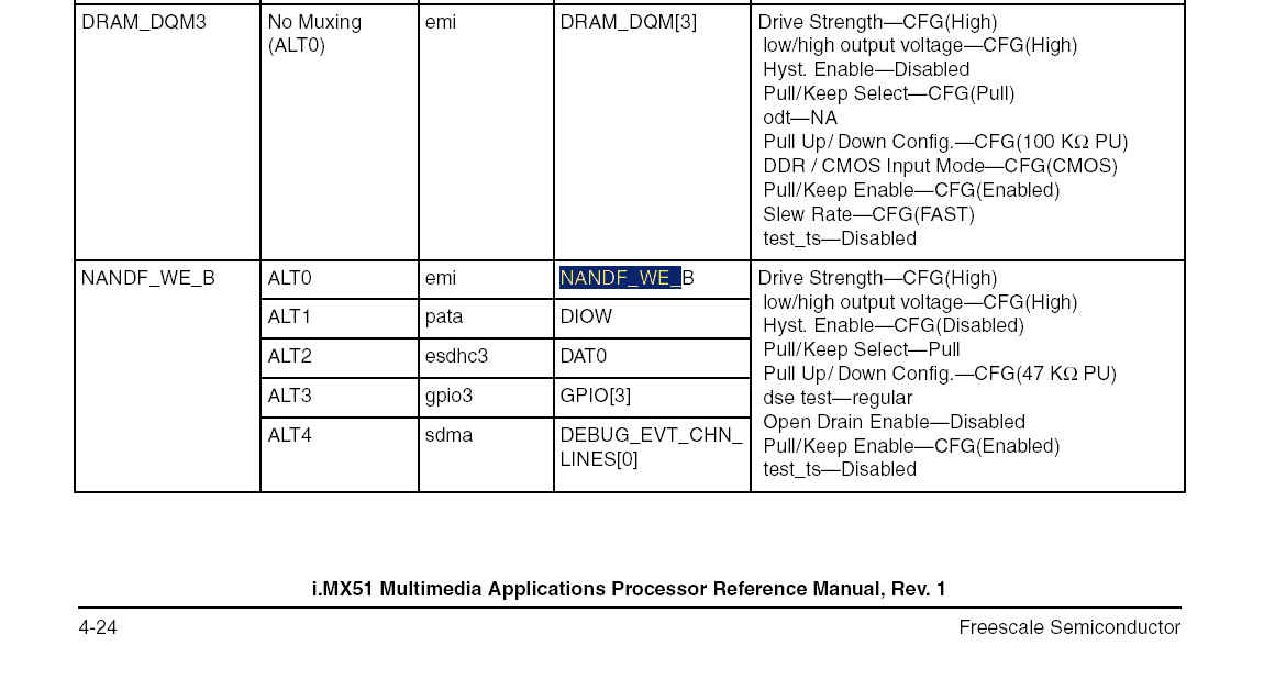
I just recently noticed the attached JPEG from the Security Manual. It is showing the eSDHC3 connected to different pins that we are using. But it also looks like this document has some errors. It looks like it has the CMD and CLK pins are swapped for the eSDHC3. Can you confirm this?
We have our DAT0 pin connected to NANDF_DAT8 while the security document has it connected to NANDF_WE_B. Assuming the ROM is expecting this and setting the IOMUX registers accordingly, what options do have for correcting this? Can the ROM be changed to support the pin we are using? Can you point me to the documents that walk us through the ROM modification and reprogramming?
When we attempt to boot, we are not seeing any activity on the CLK or CMD lines. Is there something else we are missing that would prevent this access? Again, we are setting our straps as above and not using any eFUSES.
Thanks for the help.
Wayne
- 新着としてマーク
- ブックマーク
- 購読
- ミュート
- RSS フィードを購読する
- ハイライト
- 印刷
- 不適切なコンテンツを報告
Hi Wayne
yes in jpeg CMD and CLK pins are swapped for the eSDHC3.
Regarding DAT0 pin - in current RM it is connected to NANDF_WE_B,
please check attached file.
ROM can not be changed to support the other pins.
Actually you always should check fuses (may be they are inadvertently blown)
[by jtag] and verify that you are really booting from boot pins.
SRC Boot Mode Register (SBMR) reflects the status of boot
mode pins.
Best regards
chip
- 新着としてマーク
- ブックマーク
- 購読
- ミュート
- RSS フィードを購読する
- ハイライト
- 印刷
- 不適切なコンテンツを報告
We have been reading a register at offset 0x4 to confirm the bootstraps. I assume any eFUSE changes would be seen there.
It looks like we need to change our layout to support DAT0 at NANDF_WE_B. Are there any other options? How about the other pins, can you give me the recommended locations for the other data lines? We do not have access to the Security Manual.
We are seeing a value of 0x00000002 for the NANDF_RB0. Can you comment on that? It is confusing our software engineer.
How does BT_BUS_WIDTH effect the eSDHC? We have found that when this strap is low we are able to see activity (o-scope) on the cmd and clk lines when we try to boot. When this strap is high, we do not see activity.
Wayne Eckertson
Sr. Hardware Engineer
The Logical Company
541-515-4737
- 新着としてマーク
- ブックマーク
- 購読
- ミュート
- RSS フィードを購読する
- ハイライト
- 印刷
- 不適切なコンテンツを報告
Hi Wayne
regarding DAT0 at NANDF_WE_B, unfortunately there are
no other options.
BT_BUS_WIDTH selects NAND/NOR Bus Width.
Actually all questions are described in i.MX51 Security Reference Manual.
Best regards
chip
- 新着としてマーク
- ブックマーク
- 購読
- ミュート
- RSS フィードを購読する
- ハイライト
- 印刷
- 不適切なコンテンツを報告
Thank you for your reply chip bit you may not have seen in my last post that I do not have access to the Security Manual. We are also in desperate need for this info ASAP. Can you call me so we can expedite our resolution? I can be reached at 541-515-4737 at any time.
Can you send me the NDA application paperwork? I requested it from tech support but I did not get a reply back.
Wayne Eckertson
Sr. Hardware Engineer
The Logical Company
541-515-4737
- 新着としてマーク
- ブックマーク
- 購読
- ミュート
- RSS フィードを購読する
- ハイライト
- 印刷
- 不適切なコンテンツを報告
Hi Wayne
sorry, unfortunately internal docs can not
be shared in public. Please work internally with
tech support.
Best regards
chip
- 新着としてマーク
- ブックマーク
- 購読
- ミュート
- RSS フィードを購読する
- ハイライト
- 印刷
- 不適切なコンテンツを報告
Can you point me to the documents or sections that will allow us to boot from our eMMC device?
We can now read and write to the eMMC but need to be able to set the hardware up to default to IOMUX settings that will connect the eSDHC3 to the pins specified. I assume there are either eFUSES or a way to update the ROM to setup this configuration. Where can I find detailed info on how to set the eFUSES or update the ROM?
Thanks again for the help.
Wayne
- 新着としてマーク
- ブックマーク
- 購読
- ミュート
- RSS フィードを購読する
- ハイライト
- 印刷
- 不適切なコンテンツを報告
He Wayne
for fuses [or boot pins] configuration one can refer to Boot Chapter
MCIMX51 Multimedia Applications Processor Reference Manual
and refer to attached file (only DAT0 is available when the SD/MMC is
used for boot. The remaining lines (DAT1–DAT7) are not available.)
This file is part of i.MX51 Security Reference Manual, you can request
it entering ticket to tech support.
Best regards
chip
- 新着としてマーク
- ブックマーク
- 購読
- ミュート
- RSS フィードを購読する
- ハイライト
- 印刷
- 不適切なコンテンツを報告
I just recently noticed the attached JPEG from the Security Manual. It is showing the eSDHC3 connected to different pins that we are using. But it also looks like this document has some errors. It looks like it has the CMD and CLK pins are swapped for the eSDHC3. Can you confirm this?
We have our DAT0 pin connected to NANDF_DAT8 while the security document has it connected to NANDF_WE_B. Assuming the ROM is expecting this and setting the IOMUX registers accordingly, what options do have for correcting this? Can the ROM be changed to support the pin we are using? Can you point me to the documents that walk us through the ROM modification and reprogramming?
When we attempt to boot, we are not seeing any activity on the CLK or CMD lines. Is there something else we are missing that would prevent this access? Again, we are setting our straps as above and not using any eFUSES.
Thanks for the help.
Wayne
- 新着としてマーク
- ブックマーク
- 購読
- ミュート
- RSS フィードを購読する
- ハイライト
- 印刷
- 不適切なコンテンツを報告
I have been reading the reference manual but have not been able to figure out how to set the IOMUX registers are set for booting. We know we need to and have been setting these registers to bring the eSDHC3 signals out of NAND bus pins. We can successfully read and write to the device after we boot from a JTAG device. But how does the system set these registers when you want to boot from the onboard eMMC device?
Does the on board ROM set these registers automatically based on the BT_MEM_CTL, BT_MEM_TYPE, and BT_SRC strappings? We have tried setting these but are not seeing any activity on our CLK/CMD lines when we try to boot.
We have set the following strapping...
BT_MEM_CTL1 - High
BT_MEM_CTL0 - High
BT_MEM_TYPE1 - Low
BT_MEM_TYPE0 - Low
BT_SRC1 - High
BT_SRC0 - Low
Can you or someone else provide some more detailed assistance?
Wayne
- 新着としてマーク
- ブックマーク
- 購読
- ミュート
- RSS フィードを購読する
- ハイライト
- 印刷
- 不適切なコンテンツを報告
He Wayne
I would suggest to start with :
AN4173 U-Boot for i.MX51 Based Designs,
Chapter 15 Adding Support for the i.MX53 eSDHC
MX53UG i.MX53 System Development User’s Guide
(actually i.MX51 and i.MX53 Linux/Uboot codes are very similar)
L2.6.35_10.11_ER_SOURCE : Linux 2.6.35 Source Code Files
For reference it may be useful to look at i.MX53 QSB schematic (SPF-27104_B.pdf, p8)
it has SD3 on board and its Linux/Uboot codes
MCIMX53-START-R i.MX53 QS Board Schematics :
L2.6.35_11_09_ER_SOURCE : Linux 2.6.35 Source Code Files
Best regards
chip
-----------------------------------------------------------------------------------------------------------------------
Note: If this post answers your question, please click the Correct Answer button. Thank you!
-----------------------------------------------------------------------------------------------------------------------
- 新着としてマーク
- ブックマーク
- 購読
- ミュート
- RSS フィードを購読する
- ハイライト
- 印刷
- 不適切なコンテンツを報告
Thank you chip. This is a good starting place for me.
Wayne