
- NXP Forums
- Product Forums
- General Purpose MicrocontrollersGeneral Purpose Microcontrollers
- i.MX Forumsi.MX Forums
- QorIQ Processing PlatformsQorIQ Processing Platforms
- Identification and SecurityIdentification and Security
- Power ManagementPower Management
- MCX Microcontrollers
- S32G
- S32K
- S32V
- MPC5xxx
- Other NXP Products
- Wireless Connectivity
- S12 / MagniV Microcontrollers
- Powertrain and Electrification Analog Drivers
- Sensors
- Vybrid Processors
- Digital Signal Controllers
- 8-bit Microcontrollers
- ColdFire/68K Microcontrollers and Processors
- PowerQUICC Processors
- OSBDM and TBDML
-
- Solution Forums
- Software Forums
- MCUXpresso Software and ToolsMCUXpresso Software and Tools
- CodeWarriorCodeWarrior
- MQX Software SolutionsMQX Software Solutions
- Model-Based Design Toolbox (MBDT)Model-Based Design Toolbox (MBDT)
- FreeMASTER
- eIQ Machine Learning Software
- Embedded Software and Tools Clinic
- S32 SDK
- S32 Design Studio
- Vigiles
- GUI Guider
- Zephyr Project
- Voice Technology
- Application Software Packs
- Secure Provisioning SDK (SPSDK)
- Processor Expert Software
-
- Topics
- Mobile Robotics - Drones and RoversMobile Robotics - Drones and Rovers
- NXP Training ContentNXP Training Content
- University ProgramsUniversity Programs
- Rapid IoT
- NXP Designs
- SafeAssure-Community
- OSS Security & Maintenance
- Using Our Community
-
- Cloud Lab Forums
-
- Home
- :
- Product Forums
- :
- Sensors
- :
- MPR121 Touch Pad Schematic Review
MPR121 Touch Pad Schematic Review
- Subscribe to RSS Feed
- Mark Topic as New
- Mark Topic as Read
- Float this Topic for Current User
- Bookmark
- Subscribe
- Mute
- Printer Friendly Page
- Mark as New
- Bookmark
- Subscribe
- Mute
- Subscribe to RSS Feed
- Permalink
- Report Inappropriate Content
Dear All,
One of my customer wants develop a touchpad for their end product. Below is the customer requirement.
1. 4 Touch Pad
2. 4 LED Indication
3. I2C interface for host processor
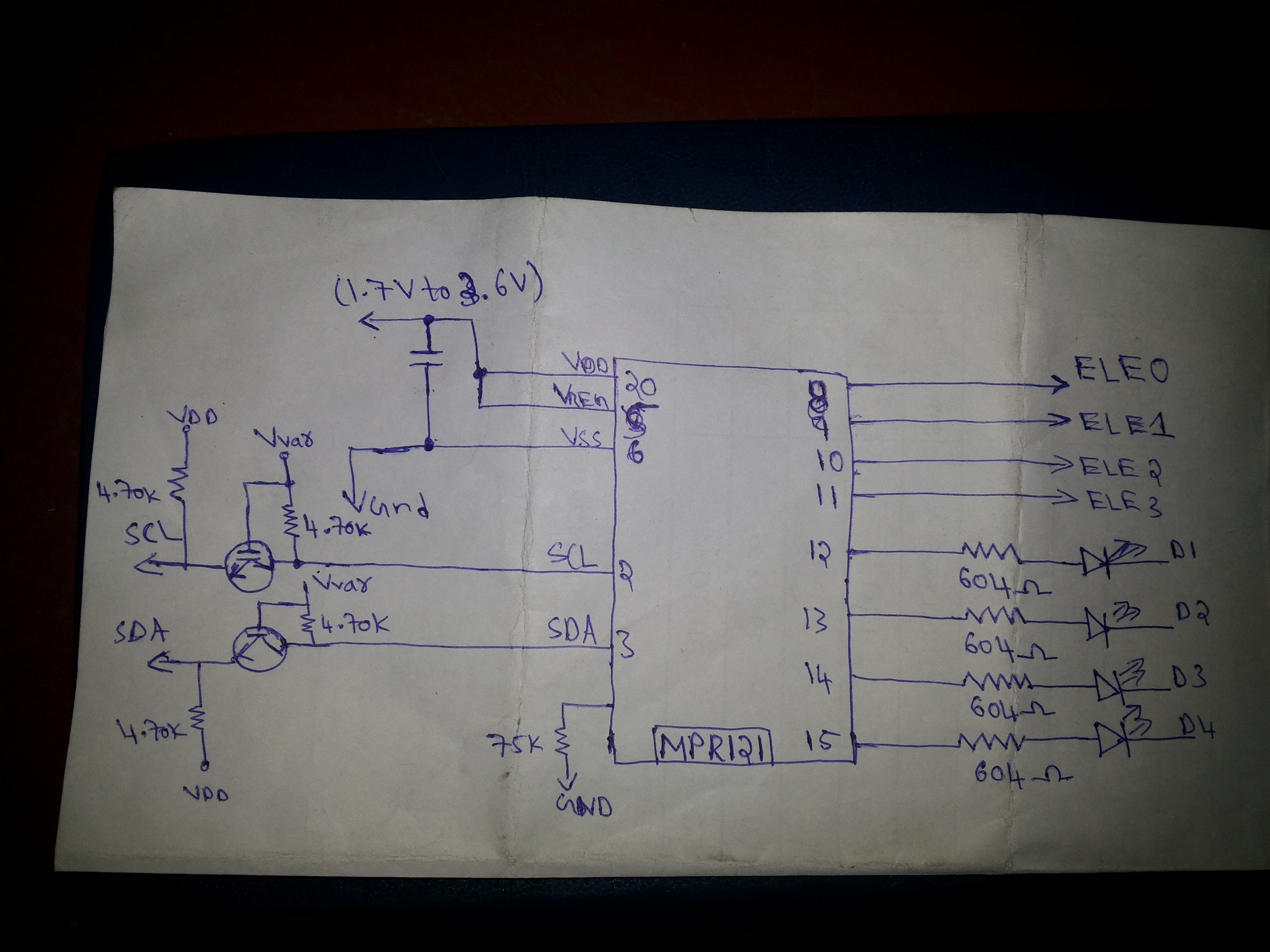
I'm promoting MPR121 and have made a rough schematic for total BOM conclusion. Please review my schematic and suggest if any changes needs to be done.
Thanks in advance
Regards
Mithun
FAE
WTMEC
Solved! Go to Solution.
- Mark as New
- Bookmark
- Subscribe
- Mute
- Subscribe to RSS Feed
- Permalink
- Report Inappropriate Content
Mithun,
Looks fine, just a few comments:
1. As VDD is higher than 2.75V, the VDD and VREG pins should not be connected together. Use a separate 0.1μF decoupling ceramic capacitor on VREG to VSS as shown in figure 2 of the datasheet.
2. In the final schematic, do not forget to connect the ADDR pin accordingly.
3. If the customer is going to use the IRQ output, use a level translator also on this line. I do not have much experience with discrete MOSFETs, I usually use an integrated solution such as the PCA9306DCUR from TI.
Regards,
Tomas
- Mark as New
- Bookmark
- Subscribe
- Mute
- Subscribe to RSS Feed
- Permalink
- Report Inappropriate Content
- Mark as New
- Bookmark
- Subscribe
- Mute
- Subscribe to RSS Feed
- Permalink
- Report Inappropriate Content
Hi Mithun,
Two comments:
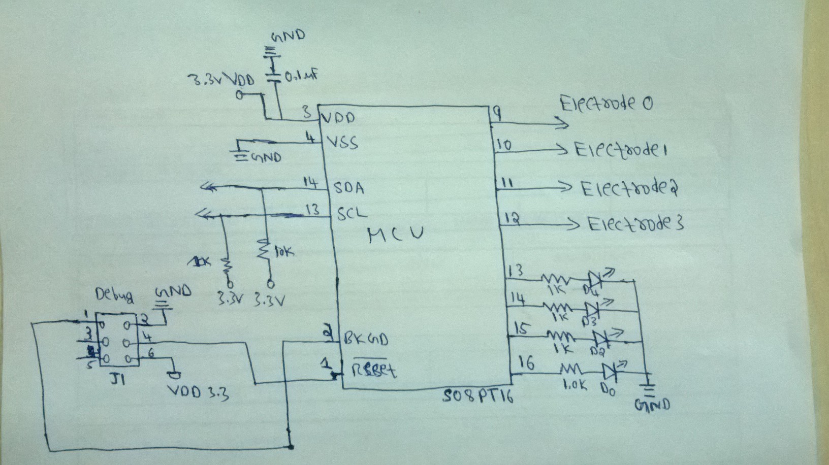
1. Both PTA2 (SDA) and PTA3 (SCL) pins are used for I2C communication, so you cannot use them to drive LED3 and LED4. Use PTB4 and PTB5 pins to drive these LEDs.
2. In the final schematic, do not forget to connect a crystal or ceramic resonator to the XTAL and EXTAL pins as shown in Figure 2-7 of the MC9S08PT16 Reference Manual, unless you make use of the internal reference within the MC9S08PT16.
Regards,
Tomas
- Mark as New
- Bookmark
- Subscribe
- Mute
- Subscribe to RSS Feed
- Permalink
- Report Inappropriate Content
Dear Tomas,
I will make use of Internal clock.
Regards
Mithun