
- Forums
- Product Forums
- General Purpose MicrocontrollersGeneral Purpose Microcontrollers
- i.MX Forumsi.MX Forums
- QorIQ Processing PlatformsQorIQ Processing Platforms
- Identification and SecurityIdentification and Security
- Power ManagementPower Management
- Wireless ConnectivityWireless Connectivity
- RFID / NFCRFID / NFC
- Advanced AnalogAdvanced Analog
- Neural Processing UnitsNeural Processing Units
- MCX Microcontrollers
- S32G
- S32K
- S32V
- MPC5xxx
- Other NXP Products
- S12 / MagniV Microcontrollers
- Powertrain and Electrification Analog Drivers
- Sensors
- Vybrid Processors
- Digital Signal Controllers
- 8-bit Microcontrollers
- ColdFire/68K Microcontrollers and Processors
- PowerQUICC Processors
- OSBDM and TBDML
- S32M
- S32Z/E
-
- Solution Forums
- Software Forums
- MCUXpresso Software and ToolsMCUXpresso Software and Tools
- CodeWarriorCodeWarrior
- MQX Software SolutionsMQX Software Solutions
- Model-Based Design Toolbox (MBDT)Model-Based Design Toolbox (MBDT)
- FreeMASTER
- eIQ Machine Learning Software
- Embedded Software and Tools Clinic
- S32 SDK
- S32 Design Studio
- GUI Guider
- Zephyr Project
- Voice Technology
- Application Software Packs
- Secure Provisioning SDK (SPSDK)
- Processor Expert Software
- Generative AI & LLMs
-
- Topics
- Mobile Robotics - Drones and RoversMobile Robotics - Drones and Rovers
- NXP Training ContentNXP Training Content
- University ProgramsUniversity Programs
- Rapid IoT
- NXP Designs
- SafeAssure-Community
- OSS Security & Maintenance
- Using Our Community
-
- Cloud Lab Forums
-
- Knowledge Bases
- ARM Microcontrollers
- i.MX Processors
- Identification and Security
- Model-Based Design Toolbox (MBDT)
- QorIQ Processing Platforms
- S32 Automotive Processing Platform
- Wireless Connectivity
- CodeWarrior
- MCUXpresso Suite of Software and Tools
- MQX Software Solutions
- RFID / NFC
- Advanced Analog
- Neural Processing Units
-
- NXP Tech Blogs
- Home
- :
- Product Forums
- :
- Sensors
- :
- MPL115A1 DOUT not work
MPL115A1 DOUT not work
- Subscribe to RSS Feed
- Mark Topic as New
- Mark Topic as Read
- Float this Topic for Current User
- Bookmark
- Subscribe
- Mute
- Printer Friendly Page
As of February 2, 2026, the NXP MEMS Sensor products have been transferred to STMicroelectronics. For details on the transferred products, see this page. Please reach out to STMicroelectronics for further information.
MPL115A1 DOUT not work
- Mark as New
- Bookmark
- Subscribe
- Mute
- Subscribe to RSS Feed
- Permalink
- Report Inappropriate Content
I have connected MPL115A1 as per data sheet and not using shutdown option so it is connected VDD.
I am trying to read coefficient and ADC data via SPI bus.
I am sending following packets:
start conversion and wait for 3ms.
Read Pressure ADC (MSB and LSB)
Read Temp ADC (MSB and LSB)
Read A0 (MSB and LSB)
Read B1 (MSB and LSB)
Read B2 (MSB and LSB)
Read C12 (MSB and LSB)
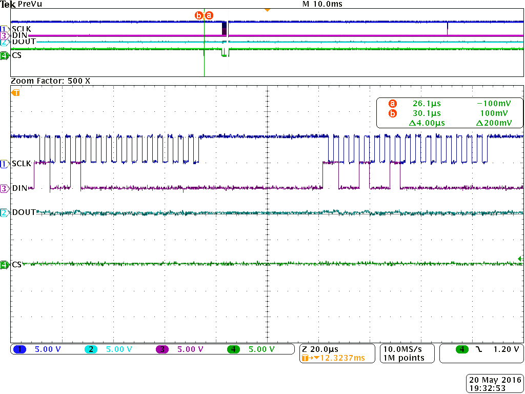
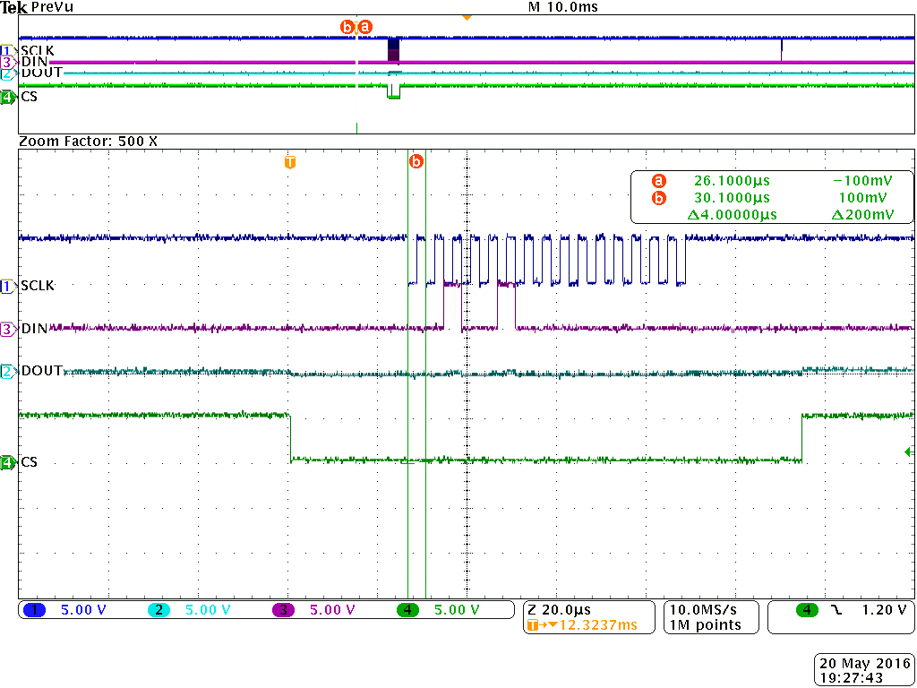
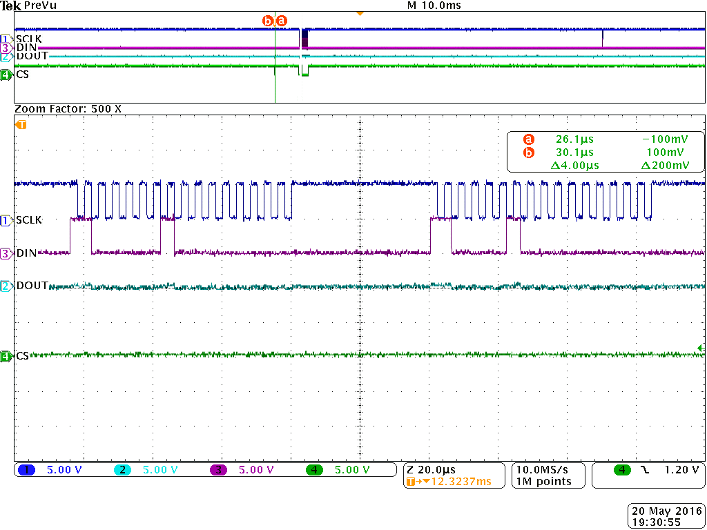
I have attached screen shot of SCLK, CS, DOUT and DIN lines
Surprisingly I can't see any data on DOUT.
Also, I have tried to disconnect DOUT from rest of ckt and probed on MPL115A1 Pin 6. Though I can't see any data coming out. I have tried another IC incase first one is not working!! No improvement.
Any help?
- Mark as New
- Bookmark
- Subscribe
- Mute
- Subscribe to RSS Feed
- Permalink
- Report Inappropriate Content
Just wonder whether I got correct ICs from supplier or not?
It has marking M1PR COC (or M1PR C0C).
- Mark as New
- Bookmark
- Subscribe
- Mute
- Subscribe to RSS Feed
- Permalink
- Report Inappropriate Content
Hi Dhaval,
Yes, M1PR is the correct marking for the MPL115A1 (SPI version), M2PR is for the MPL115A2 (I2C version). The next 3 signs denote the production series.
The timing seems to be correct now. If you ordered more MPL115A1 parts, have you tried using another device? Could you please post here your schematic to make sure the problem is not there?
Regards,
Tomas
- Mark as New
- Bookmark
- Subscribe
- Mute
- Subscribe to RSS Feed
- Permalink
- Report Inappropriate Content
Hi Tomas,
I have tried this as well. No luck.


Not adding all Screen shots.
- Mark as New
- Bookmark
- Subscribe
- Mute
- Subscribe to RSS Feed
- Permalink
- Report Inappropriate Content
Hi Dhaval,
I assume the problem is in the base value of the clock (SCLK). The MPL115A1 uses the ‘Mode 0′ SPI protocol, which means that an inactive state of clock signal should be low and not high. If you use a hardware SPI, it corresponds to CPOL = 0 setting.
I hope it helps. If not, please let me know and I will continue in investigating this issue.
Regards,
Tomas
PS: If my answer helps to solve your question, please mark it as "Correct". Thank you.
- Mark as New
- Bookmark
- Subscribe
- Mute
- Subscribe to RSS Feed
- Permalink
- Report Inappropriate Content
Hi Tomas,
Thanks for reply. I have tried mode 0 but no luck. (not adding all screen shot here)


- Mark as New
- Bookmark
- Subscribe
- Mute
- Subscribe to RSS Feed
- Permalink
- Report Inappropriate Content
Hi Dhaval,
Looking at your screenshots, the clock signal is now correct, but the data are captured on the falling edge which is incorrect. Make sure that the data are captured on the leading edge of clock signal and changed on the falling edge (Mode 0 – CPOL = 0 and CPHA = 0).

I hope this helps.
Regards,
Tomas