
- NXP Forums
- Product Forums
- General Purpose MicrocontrollersGeneral Purpose Microcontrollers
- i.MX Forumsi.MX Forums
- QorIQ Processing PlatformsQorIQ Processing Platforms
- Identification and SecurityIdentification and Security
- Power ManagementPower Management
- MCX Microcontrollers
- S32G
- S32K
- S32V
- MPC5xxx
- Other NXP Products
- Wireless Connectivity
- S12 / MagniV Microcontrollers
- Powertrain and Electrification Analog Drivers
- Sensors
- Vybrid Processors
- Digital Signal Controllers
- 8-bit Microcontrollers
- ColdFire/68K Microcontrollers and Processors
- PowerQUICC Processors
- OSBDM and TBDML
-
- Solution Forums
- Software Forums
- MCUXpresso Software and ToolsMCUXpresso Software and Tools
- CodeWarriorCodeWarrior
- MQX Software SolutionsMQX Software Solutions
- Model-Based Design Toolbox (MBDT)Model-Based Design Toolbox (MBDT)
- FreeMASTER
- eIQ Machine Learning Software
- Embedded Software and Tools Clinic
- S32 SDK
- S32 Design Studio
- Vigiles
- GUI Guider
- Zephyr Project
- Voice Technology
- Application Software Packs
- Secure Provisioning SDK (SPSDK)
- Processor Expert Software
-
- Topics
- Mobile Robotics - Drones and RoversMobile Robotics - Drones and Rovers
- NXP Training ContentNXP Training Content
- University ProgramsUniversity Programs
- Rapid IoT
- NXP Designs
- SafeAssure-Community
- OSS Security & Maintenance
- Using Our Community
-
-
- Home
- :
- Product Forums
- :
- Sensors
- :
- MMA8452Q - Questions about readings and read values
MMA8452Q - Questions about readings and read values
- Subscribe to RSS Feed
- Mark Topic as New
- Mark Topic as Read
- Float this Topic for Current User
- Bookmark
- Subscribe
- Mute
- Printer Friendly Page
MMA8452Q - Questions about readings and read values
- Mark as New
- Bookmark
- Subscribe
- Mute
- Subscribe to RSS Feed
- Permalink
- Report Inappropriate Content
Hi,
I have two questions/problems with MMA8452Q readings and I would be grateful for explanations.
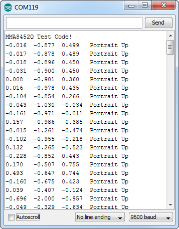
- I am using this accelerometer with my Teensy board which is Arduino comaptible. That means I can use also all the libraries. So I am using Sparkfun's library: MMA8452_Accelerometer/Firmware/libraries/SFE_MMA8452Q at master · sparkfun/MMA8452_Accelerometer · G.... After modification in this code thanks to the Tomas Vaverka and his answer to my previous question (MMA8452Q - Strange reading values) I was able to fix no negative value error. But now when I am looking again at the readings displayed at the Sarkfun webpage I think that still I have something wrong and to be honest, don't know why (my readings are included in the file).
My current reading value code in library looks like that:// in header file: short x, y, z; x = ((short)(rawData[0]<<8 | rawData[1])) >> 4; y = ((short)(rawData[2]<<8 | rawData[3])) >> 4; z = ((short)(rawData[4]<<8 | rawData[5])) >> 4; cx = (float) x / (float)(scale); cy = (float) y / (float)(scale); cz = (float) z / (float)(scale);
I have sensitivity (scale) set to 2g. What is wrong in my code? - Second question is not so strong connected to source code or any error (to my knowledge). In documentation I found out that there are in fact 2 registers that holds 12 bit data. However, both in libaray and in Tomas Vaverka code (MMA8652FC - Bare metal example project) there is only getting value from 6 bits. Only thinkg that I found and might be an answer, but I don't fully understand it is the paragraph at the bottom of 20th page in documentation:
OUT_X_MSB, OUT_X_LSB, OUT_Y_MSB, OUT_Y_LSB, OUT_Z_MSB, and OUT_Z_LSB are stored in the autoincrementing address range of 0x01 to 0x06 to reduce reading the status followed by 12-bit axis data to 7 bytes. If the F_READ bit is set (0x2A bit 1), auto-increment will skip over LSB registers. This will shorten the data acquisition from 7 bytes to 4 bytes. The LSB registers can only be read immediately following the read access of the corresponding MSB register. A random read access to the LSB registers is not possible. Reading the MSB register and then the LSB register in sequence ensures that both bytes (LSB and MSB) belong to the same data sample, even if a new data sample arrives between reading the MSB and the LSB byte.
Can someone explain me why we are reading only 6 bits and in those bits there is value of 12 bits? Or do I understand it wrong?
Original Attachment has been moved to: data.txt.zip
- Mark as New
- Bookmark
- Subscribe
- Mute
- Subscribe to RSS Feed
- Permalink
- Report Inappropriate Content
Hi Sebastian,
Have you tried performing a simple test without using the acceleration data? For instance, try to assign:
1. A value of 0x40 to the rawData[0] and 0x00 to the rawData[1]. Then your signed 16-bit variable named x should equal 0x0400 (1024) and the corresponding float variable named cx +1.0 considering scale = 1024.
2. A value of 0xC0 to the rawData[0] and 0x00 to the rawData[1]. Then your signed 16-bit variable named x should equal 0x0C00 (-1024) and the corresponding float variable named cx -1.0 considering scale = 1024.
If you are getting different values, you will need to adjust your conversion routines.
I am not sure about your second question, what do you mean by “getting value from 6 bits”? In my example project as well as in the Sparkfun’s library, the six bytes (raw data registers 0x01 [OUT_X_MSB] – 0x06 [OUT_Z_LSB]) are read in sequence and then used to calculate both the signed 12-bit values and real values in g’s.
I hope it helps.
Regards,
Tomas
PS: If my answer helps to solve your question, please mark it as "Correct" or “Helpful”. Thank you.