
- Forums
- Product Forums
- General Purpose MicrocontrollersGeneral Purpose Microcontrollers
- i.MX Forumsi.MX Forums
- QorIQ Processing PlatformsQorIQ Processing Platforms
- Identification and SecurityIdentification and Security
- Power ManagementPower Management
- Wireless ConnectivityWireless Connectivity
- RFID / NFCRFID / NFC
- Advanced AnalogAdvanced Analog
- Neural Processing UnitsNeural Processing Units
- MCX Microcontrollers
- S32G
- S32K
- S32V
- MPC5xxx
- Other NXP Products
- S12 / MagniV Microcontrollers
- Powertrain and Electrification Analog Drivers
- Sensors
- Vybrid Processors
- Digital Signal Controllers
- 8-bit Microcontrollers
- ColdFire/68K Microcontrollers and Processors
- PowerQUICC Processors
- OSBDM and TBDML
- S32M
- S32Z/E
-
- Solution Forums
- Software Forums
- MCUXpresso Software and ToolsMCUXpresso Software and Tools
- CodeWarriorCodeWarrior
- MQX Software SolutionsMQX Software Solutions
- Model-Based Design Toolbox (MBDT)Model-Based Design Toolbox (MBDT)
- FreeMASTER
- eIQ Machine Learning Software
- Embedded Software and Tools Clinic
- S32 SDK
- S32 Design Studio
- GUI Guider
- Zephyr Project
- Voice Technology
- Application Software Packs
- Secure Provisioning SDK (SPSDK)
- Processor Expert Software
- Generative AI & LLMs
-
- Topics
- Mobile Robotics - Drones and RoversMobile Robotics - Drones and Rovers
- NXP Training ContentNXP Training Content
- University ProgramsUniversity Programs
- Rapid IoT
- NXP Designs
- SafeAssure-Community
- OSS Security & Maintenance
- Using Our Community
-
- Cloud Lab Forums
-
- Knowledge Bases
- ARM Microcontrollers
- i.MX Processors
- Identification and Security
- Model-Based Design Toolbox (MBDT)
- QorIQ Processing Platforms
- S32 Automotive Processing Platform
- Wireless Connectivity
- CodeWarrior
- MCUXpresso Suite of Software and Tools
- MQX Software Solutions
- RFID / NFC
- Advanced Analog
- Neural Processing Units
-
- NXP Tech Blogs
- Home
- :
- 製品フォーラム
- :
- S12 / MagniVマイクロコントローラ
- :
- Re: FOC Model IDRequest and IQRequest
FOC Model IDRequest and IQRequest
- RSS フィードを購読する
- トピックを新着としてマーク
- トピックを既読としてマーク
- このトピックを現在のユーザーにフロートします
- ブックマーク
- 購読
- ミュート
- 印刷用ページ
FOC Model IDRequest and IQRequest
- 新着としてマーク
- ブックマーク
- 購読
- ミュート
- RSS フィードを購読する
- ハイライト
- 印刷
- 不適切なコンテンツを報告
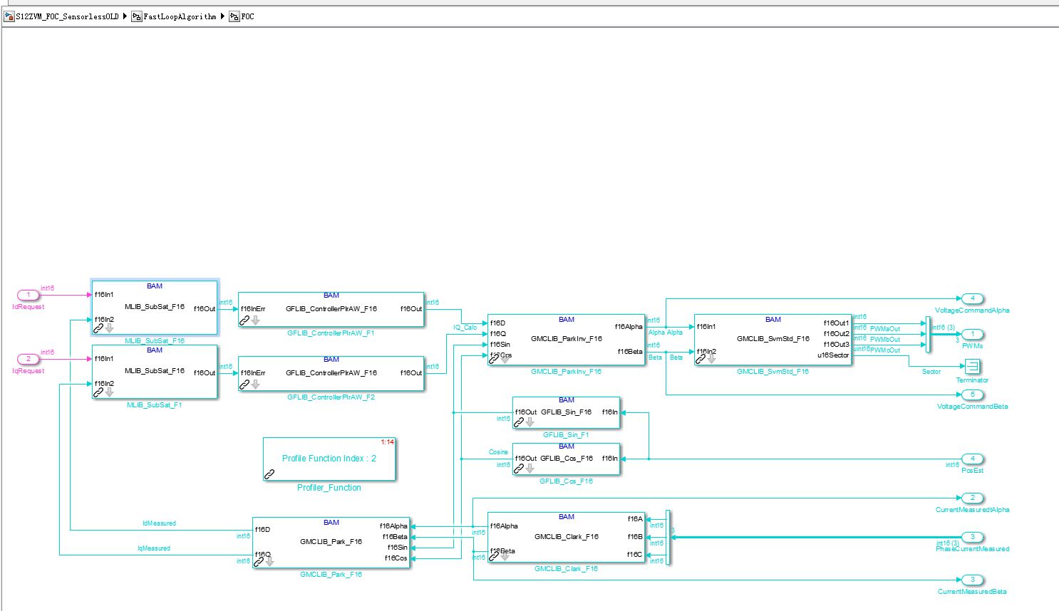
Does anybody knows the values of the two variables in FOC model.
IDRequest and IQRequest are two variables in FOC model, which will generate final PWM signal output.
And the PWM signal will make the FOC motor rotate or not.
I need the values if you have.
Or tell me the range of data, which will make the PWM module generate PWM signals.
Thanks.
- 新着としてマーク
- ブックマーク
- 購読
- ミュート
- RSS フィードを購読する
- ハイライト
- 印刷
- 不適切なコンテンツを報告


The second pictures info means: current webpage happen mistakes
Line number: 87
char 6
error: missing object
code: 0
URL: file://...
do you need to continue to run this script on this webpage?
button one is Yes, button two is No

my mini ml128 board photoshot

SCI port cannot beed detected even I opened the power supply.
Let me know your email address, I can photo my whole development system to you.
Many thanks!
Let me know your idea for this freemaster D.O.A situation.
:smileyhappy:
- 新着としてマーク
- ブックマーク
- 購読
- ミュート
- RSS フィードを購読する
- ハイライト
- 印刷
- 不適切なコンテンツを報告
Hi,
Regarding the communication - the OSBDM/OSJTAG - CDC Serial Port driver is needed to connect the board via USB. The comm speed is 19200 Bd. This way, no additional USB-to-SCI converter is needed. For this case jumpers J6 and J8 are set for 1-2 connection. If you cannot find such driver on your computer, please visit PEmicro - P&E Microcomputer Systems: Over 30 years as an Industry leader in Embedded Systems Develop... and update your drivers.

If you are using your own USB-to-SCI converter, then you would probably connect via J7 connector, while the jumpers J6 and J8 would be configured to 2-3. Even then, the communication speed is 19200 Bd.
The error messages mentioning JavaScript may be caused by missing connection, however based on my experience it is caused mainly by old version of the MS Internet Explorer (I'm using version 11.1266.15063.0).
Even if the script error appears, you can click YES to continue.
And - if you would like to have the LED diode to indicate the status of the application, you would need to enable the J5 jumper. It is not critical to the application, however it is good to have it :smileyhappy:
Best regards
Matej
- 新着としてマーク
- ブックマーク
- 購読
- ミュート
- RSS フィードを購読する
- ハイライト
- 印刷
- 不適切なコンテンツを報告

I did exactly according to what you mentioned above. However, I found OSBDM needs exact hardware driver.
Because the OSBDM in my win7 x64 control panel have warning flags. I do not it is a problem for correct connection.
And I searched the website and did not found any ML128 mini board hardware drivers for downloading.
What kind of driver you installed on your computer? PL232 usb to serial port driver only?
Let me know your NXP driver package download http link if you have.
Many Thanks!
- 新着としてマーク
- ブックマーク
- 購読
- ミュート
- RSS フィードを購読する
- ハイライト
- 印刷
- 不適切なコンテンツを報告
Hi,
The warning flags may be the problem.
Just a quick internet search for "PE Micro OSBDM" gives me following result:
On the page, I can click to download the Windows drivers:
http://www.pemicro.com/downloads/download_file.cfm?download_id=53
This is all I got. It worked on Win7 as well as it works now on Win10. If it doesn't work, I suggest you to start a new thread and ask my technical support colleagues to help you.
Best regards
Matej
- 新着としてマーク
- ブックマーク
- 購読
- ミュート
- RSS フィードを購読する
- ハイライト
- 印刷
- 不適切なコンテンツを報告
I did exactly according to above you mentioned. And the yellow warning flags disappeared now.
The freemaster project could not detect the motherboard voltage.
And there is a mistake in the FOC control webpage.

System requires clear fault. My motor did roate for a while. But it never rotate again when clear fault appeared.
How to clear fault?
Do I need to modify my PMSM motor configuration parameters?
My current setting is below:


Let me know where I should modify my parameters or corresponding settings to make my DC motor rotate without any fault again.
Many Thanks!
- 新着としてマーク
- ブックマーク
- 購読
- ミュート
- RSS フィードを購読する
- ハイライト
- 印刷
- 不適切なコンテンツを報告
Hi,
Maybe it is caused by me exporting the project to a zip file. Can you please go to the settings of the FreeMASTER project and check the following?

Even if the setting is the same (mainly the Default symbol file path), please click on the [ ... ] button and browse to your CodeWarrior project directory, FLASH folder and select the AN5327_SW_CW10.elf. Then click OK and test it again.
BR
Matej
- 新着としてマーク
- ブックマーク
- 購読
- ミュート
- RSS フィードを購読する
- ハイライト
- 印刷
- 不適切なコンテンツを報告

Hi Matej,
The above picture is my side configuration for freemaster.
I think there is no any problem with the configuration.
Maybe I need to change the cables for the motor because the mental line is too thin to load a very big current.
My another major problem is the SCI port.
I still could not connect my mini board with my usb to serial port cable.
According to we discussed previsouly, we configured J6 and J8 from 1-2 to 2-3 and then set the baud rate is 19200, then I check the usb serial port number is exact com4 in my hardware manager in local control panel.
But, when I connected my miniboard with the usb-serial port, it always shew no any board detected. I am doubt in your side, your serial port work good or not?
If yes, what is your configuration for usb2serial cable?
Many thanks!
- 新着としてマーク
- ブックマーク
- 購読
- ミュート
- RSS フィードを購読する
- ハイライト
- 印刷
- 不適切なコンテンツを報告
Hello,
Let's make your issues in two clear ones:
#1: The device is not communicating with the FreeMASTER via built-in OSBDM with CDC USB-to-SCI
- please create a separate thread on community. I cannot help you with it. The code I have provided works for me as well as for my colleague on his computer. Your issue may be wrong P&E Micro drivers or even a HW issue.
#2: The FOC code requires the motor parameters and also some tuning to be done using MCAT (the FreeMASTER plugin you have already). But without working connection between the FreeMASTER and the board, we can do nothing.
Thank you,
BR
Matej
- 新着としてマーク
- ブックマーク
- 購読
- ミュート
- RSS フィードを購読する
- ハイライト
- 印刷
- 不適切なコンテンツを報告
Ok. I will open another new thread for SCI issue.
But I need to make it clear the communicating with the FreeMASTER via built-in OSBDM is perfect, absolutely no any problem.
But after we use usb2db9 cable to communite with the mini board according to you mentioned j6 j8 were configured from 1-2 to 2-3 and the speed was set to 19200 exactly, the serial port always failed.
The question is why the OSBDM connected no problem but the usb2serial port always failed.
- 新着としてマーク
- ブックマーク
- 購読
- ミュート
- RSS フィードを購読する
- ハイライト
- 印刷
- 不適切なコンテンツを報告
Hi Matej,
Do you get any good news for your timer problem?
- 新着としてマーク
- ブックマーク
- 購読
- ミュート
- RSS フィードを購読する
- ハイライト
- 印刷
- 不適切なコンテンツを報告
Hi,
finally I got some time to make a package. It is nothing more, just the general AN5327 example software slightly edited to fit in the MINIBRD.
https://community.nxp.com/docs/DOC-341536
Please let me know if it works for you.
Best regards,
Matej
- 新着としてマーク
- ブックマーク
- 購読
- ミュート
- RSS フィードを購読する
- ハイライト
- 印刷
- 不適切なコンテンツを報告
Hi,
sorry for the delay, but I'm still on a long business trip, not able to test anything. I would check for the final bus clock settings, either by evaluating some GPIO changed periodically by a timer or by verifying the SCI baudrate.
BR
Matej
- 新着としてマーク
- ブックマーク
- 購読
- ミュート
- RSS フィードを購読する
- ハイライト
- 印刷
- 不適切なコンテンツを報告
Hi Matej,
The javascript warning information means "Missing Object".
- incompatibility issues (Internet Explorer has been updated or is outdated, or it is the operation system issue)
My computers use IE8.0 IE9.0 which both generate object missing alert. What is the exact version of the IE browser we should use? Can we run this demo freemaster project with windows 10 x64 os?
- one or more files of the MCAT have been changed/removed/renamed
I download the AN5372 demo project from nxp.com and install it without any change. There should not be any MCAT files were changed or removed/renamed. I do nothing but install completely.
- the MCAT settings have been changed with no reflection in the other configurations
How to correctly set MCAT. I found it is a plug in for freemaster project. I download 5327 from NXP official website and install it completely to C drive without any change.
Do you have any helpful MCAT setting resources or links?
Many thanks!
- 新着としてマーク
- ブックマーク
- 購読
- ミュート
- RSS フィードを購読する
- ハイライト
- 印刷
- 不適切なコンテンツを報告
Hi Matej,
I did add the instruction of active the internal oscillator into the program and compiled successfully. However, I found another trouble: the AN5327_PMSM_FOC_Sensorless_SingleShunt.pmp, which can not show the FOC motor control page completely. And it always show security alert msg which need people click "Yes" to continue it.

Furthermore, the freemaster cannot show the FOC motor web page at all as below picture:

How to solve this problem, so that I can debug my single shunt FOC motor project.
Many thanks.
- 新着としてマーク
- ブックマーク
- 購読
- ミュート
- RSS フィードを購読する
- ハイライト
- 印刷
- 不適切なコンテンツを報告
Hi,
unfortunately, I cannot read the error message in Chinese.
It looks like the java engine doesn't have access to some files. It might be either by:
- incompatibility issues (Internet Explorer has been updated or is outdated, or it is the operation system issue)
- one or more files of the MCAT have been changed/removed/renamed
- the MCAT settings have been changed with no reflection in the other configurations
Is the error reversible? This means - can you undo the changes and get the SW working again?
If you download the AN5327 software from the web and overwrite your FreeMASTER_control folder with the original folder, does it help?
Let us know :smileyhappy:
Matej
- 新着としてマーク
- ブックマーク
- 購読
- ミュート
- RSS フィードを購読する
- ハイライト
- 印刷
- 不適切なコンテンツを報告
I modified this code for the file named MC9S12ZVML128_PMSM.c because I found the demo project downloaded from
NXP official website use the external oscillator but not the internal one. And after reading the miniboard schematic I found the MCU chip of MC9S12ZVML128 use its own internal oscillator. And the external oscillator connected to a 8 bit MCU of NXP. Thus, it is necessary to modify the MC9S12ZVML128_PMSM.c file initcup() function to switch from NXP original external oscillator to the internal one.

The external oscillator for the 8 bit MCU for downloading purpose:

I added a defination instruction to the file named MC9S12ZVML128_PMSM.c:
#define _INTERNAL_CLOCK.
Also I modifed the source code for init the MCU of MC9S12ZVML
void initCPMU(void)
{
// Wait for stable supply after power up
while (GDUF_GLVLSF)
GDUF_GLVLSF = 1;
CPMUREFDIV_REFDIV = CPMU_REFDIV;
CPMUREFDIV_REFFRQ = CPMU_REFFRQ;
CPMUSYNR_SYNDIV = CPMU_SYNDIV;
CPMUSYNR_VCOFRQ = CPMU_VCOFRQ;
CPMUPOSTDIV_POSTDIV = CPMU_POSTDIV;
//#ifdef _EXTERNAL_CLOCK // I commented these 3 lines because ML128 Miniboard does not have external oscillator to use.
//CPMUOSC_OSCE = 1; //The original demo project named MC9S12ZVML128_PMSM does define CPMUOSC_OSCE, so that it always use external oscillator but in fact there is no external oscillator in the schematic.
while (CPMUIFLG_UPOSC == 0) {}; // Wait for oscillator to start up (UPOSC=1) and PLL to lock (LOCK=1)
//#endif
while (CPMUIFLG_LOCK == 0) {};
CPMURFLG = 0x60; //Clear PORF and LVRF
return;
}
I have no idea if this defination can make internal oscillator works or not.
After I modifed this source code of MC9S12ZVML128_PMSM.c in the demo project, I redownload it to MC9S12ZVML
However, I found the internal oscillator still does not work at all.
Please let me know if you have the exactly correct demo project for Mini ML128 board which can drive a single shunt resistor FOC motor.
Need your help, you are welcome to give demo projects for single foc motor or http links for single foc motor.
Many thanks!
- 新着としてマーク
- ブックマーク
- 購読
- ミュート
- RSS フィードを購読する
- ハイライト
- 印刷
- 不適切なコンテンツを報告
What is more, I modified the source code of PMSM
void initCPMU(void)
{
// Wait for stable supply after power up
while (GDUF_GLVLSF)
GDUF_GLVLSF = 1;
CPMUREFDIV_REFDIV = CPMU_REFDIV;
CPMUREFDIV_REFFRQ = CPMU_REFFRQ;
CPMUSYNR_SYNDIV = CPMU_SYNDIV;
CPMUSYNR_VCOFRQ = CPMU_VCOFRQ;
CPMUPOSTDIV_POSTDIV = CPMU_POSTDIV;
//#ifdef _EXTERNAL_CLOCK
//CPMUOSC_OSCE = 1;
while (CPMUIFLG_UPOSC == 0) {}; // Wait for oscillator to start up (UPOSC=1) and PLL to lock (LOCK=1)
#endif
while (CPMUIFLG_LOCK == 0) {};
CPMURFLG = 0x60; //Clear PORF and LVRF
return;
}
- 新着としてマーク
- ブックマーク
- 購読
- ミュート
- RSS フィードを購読する
- ハイライト
- 印刷
- 不適切なコンテンツを報告

The above Chinese JavaScript Error information means
The fileProcessing.js NO. 87 line and Char 6 "missing Object". I tried all of my computers, this kind error information all appeared when I run AN5327 dual shunt resistor project of freemaster.
My IE version are 8.0 9.0. I also open the original js file to look the js code of Line 87th as below:

The above pictures just for help you to understand the MCAT js file err information, which cannot show the motor tab corectly.
Thanks.
- 新着としてマーク
- ブックマーク
- 購読
- ミュート
- RSS フィードを購読する
- ハイライト
- 印刷
- 不適切なコンテンツを報告
Hello,
Your question is related to the FOC theory and to your motor parameters. If you don't need to understand and you just want to play with it, then you can try to set the IQRequest to some non-zero value. If the range of the current is e.g. 5 Amps (e.g. this would be the nominal speed of the motor), I would start with 0.5 Amps and increase the current slowly by 0.2 to 0.5 Amps and check if the motor is spinning. Please be aware that this mode is not a speed control - if the motor has no load attached, it will speed up freely as long as the self friction grows up with the speed.
In case you would like to understand, please follow the books covering this topic, e.g. https://onlinelibrary.wiley.com/doi/pdf/10.1002/9781119969242.ch4
Best regards,
Matej
- 新着としてマーク
- ブックマーク
- 購読
- ミュート
- RSS フィードを購読する
- ハイライト
- 印刷
- 不適切なコンテンツを報告
Hello,
I found NXP demo board for FOC motor are different. Single Shunt resistor circuit are very similar with double shunt resistor, but the code are obvious different. For example, ML128 mini board can drive not only BLDC motor but also single shunt FOC motor. However, when you need to drive FOC motor with two shunt resistors, you need to switch to AN5327 and the NXP demo project are obvious different.
Furthermore, I need to know if there is a demo source code to switch the external oscillator on the ML128 Mini Board to the ML128 MUC its own internal oscillator? For your better understanding this question, I attached an picture on this question.

Attached source code below also:
/*****************************************************************************
*
* Function: void initCPMU(void)
*
* Description: Clock, Reset and Power Management Unit configuration
*
*****************************************************************************/
void initCPMU(void)
{
// Wait for stable supply after power up
while (GDUF_GLVLSF)
{
GDUF_GLVLSF = 1;
}
CPMUREFDIV_REFDIV = CPMU_REFDIV;
CPMUREFDIV_REFFRQ = CPMU_REFFRQ;
CPMUSYNR_SYNDIV = CPMU_SYNDIV;
CPMUSYNR_VCOFRQ = CPMU_VCOFRQ;
CPMUPOSTDIV_POSTDIV = CPMU_POSTDIV;
while (CPMUIFLG_LOCK == 0)
{
}
CPMURFLG = 0x60; //Clear PORF and LVRF
}
Wait for your reply and Many thanks.