
- Forums
- Product Forums
- General Purpose MicrocontrollersGeneral Purpose Microcontrollers
- i.MX Forumsi.MX Forums
- QorIQ Processing PlatformsQorIQ Processing Platforms
- Identification and SecurityIdentification and Security
- Power ManagementPower Management
- Wireless ConnectivityWireless Connectivity
- RFID / NFCRFID / NFC
- Advanced AnalogAdvanced Analog
- MCX Microcontrollers
- S32G
- S32K
- S32V
- MPC5xxx
- Other NXP Products
- S12 / MagniV Microcontrollers
- Powertrain and Electrification Analog Drivers
- Sensors
- Vybrid Processors
- Digital Signal Controllers
- 8-bit Microcontrollers
- ColdFire/68K Microcontrollers and Processors
- PowerQUICC Processors
- OSBDM and TBDML
- S32M
- S32Z/E
-
- Solution Forums
- Software Forums
- MCUXpresso Software and ToolsMCUXpresso Software and Tools
- CodeWarriorCodeWarrior
- MQX Software SolutionsMQX Software Solutions
- Model-Based Design Toolbox (MBDT)Model-Based Design Toolbox (MBDT)
- FreeMASTER
- eIQ Machine Learning Software
- Embedded Software and Tools Clinic
- S32 SDK
- S32 Design Studio
- GUI Guider
- Zephyr Project
- Voice Technology
- Application Software Packs
- Secure Provisioning SDK (SPSDK)
- Processor Expert Software
- Generative AI & LLMs
-
- Topics
- Mobile Robotics - Drones and RoversMobile Robotics - Drones and Rovers
- NXP Training ContentNXP Training Content
- University ProgramsUniversity Programs
- Rapid IoT
- NXP Designs
- SafeAssure-Community
- OSS Security & Maintenance
- Using Our Community
-
- Cloud Lab Forums
-
- Knowledge Bases
- ARM Microcontrollers
- i.MX Processors
- Identification and Security
- Model-Based Design Toolbox (MBDT)
- QorIQ Processing Platforms
- S32 Automotive Processing Platform
- Wireless Connectivity
- CodeWarrior
- MCUXpresso Suite of Software and Tools
- MQX Software Solutions
- RFID / NFC
- Advanced Analog
-
- NXP Tech Blogs
- Home
- :
- モバイル・ロボティクス - ドローンとローバー
- :
- ロボットハードウェア
- :
- Re: RDDRONE-BMS772
RDDRONE-BMS772
- RSS フィードを購読する
- トピックを新着としてマーク
- トピックを既読としてマーク
- このトピックを現在のユーザーにフロートします
- ブックマーク
- 購読
- ミュート
- 印刷用ページ
RDDRONE-BMS772
- 新着としてマーク
- ブックマーク
- 購読
- ミュート
- RSS フィードを購読する
- ハイライト
- 印刷
- 不適切なコンテンツを報告
Please ask questions about the RDDRONE-BMS772 board and software here
- 新着としてマーク
- ブックマーク
- 購読
- ミュート
- RSS フィードを購読する
- ハイライト
- 印刷
- 不適切なコンテンツを報告

J2 is a socket for a standard 10/9 pin debug header that will work with any Segger JLINK device.
You can also make a cable to plug into the DCDLZ port and connect to a FTDI 3v3 USB2UART cable.
https://www.amazon.com/Pre-Crimped-Connectors-Pixhawk2-Pixracer-Silicone/dp/B07PBHN7TM/ref=sr_1_3?cr...
As noted, these items are included with some of the other development kits and can be re-used here.
- 新着としてマーク
- ブックマーク
- 購読
- ミュート
- RSS フィードを購読する
- ハイライト
- 印刷
- 不適切なコンテンツを報告
- 新着としてマーク
- ブックマーク
- 購読
- ミュート
- RSS フィードを購読する
- ハイライト
- 印刷
- 不適切なコンテンツを報告
Hi @Prince1,
Let me check internally about the availability of this adapter board.
Here is some more information about the DCD-LZ adapter board, including the schematic: https://nxp.gitbook.io/hovergames/rddrone-fmuk66/connectors/debug-interface-dcd-lz/dcd-lz-breakout-b...
I do know that they are usually part of a kit, I did find this UCAN board where you have the option to buy the KIT-UCANS32K1SIC.
This kit includes 2x DCD-LZ adapters, 2x FTDI-USB cable and 1x Segger Jlink mini EDU debugger (program and debug) as well.
Link to the KIT-UCANS32K1SIC: https://www.nxp.com/products/interfaces/can-transceivers/can-signal-improvement/can-sic-evaluation-b...
Kind regards,
Cis van Mierlo
- 新着としてマーク
- ブックマーク
- 購読
- ミュート
- RSS フィードを購読する
- ハイライト
- 印刷
- 不適切なコンテンツを報告
Hello @iaingalloway @cisvmierlo ,
I plan to use the BMS772 with 6s LiPo batteries, and have questions concerning the charge and discharge.
1- Is there a way to store the batteries without discharging? I see that before going into DEEPSLEEP state where the gates are open, the BMS must go through a SELF-DISCHARGE state; or if the BMS is in SLEEP state the gates are closed which also leads to discharging.
2- What is the physical process of the self-discharge?
3- Has measuring the impedance through CAN been thought of to detect if an output is connected? For example to know if gates should be open or closed in SLEEP state.
4- Is there a recommended charger to charge the batteries with a limited current? Or at least which one do you use usually?
Thank you.
- 新着としてマーク
- ブックマーク
- 購読
- ミュート
- RSS フィードを購読する
- ハイライト
- 印刷
- 不適切なコンテンツを報告
Hi @Ch_Han,
Please see https://github.com/NXPHoverGames/RDDRONE-BMS772/ for the release notes. This describes the state machine of the BMS example software.
The SLEEP state is not for storage, as in this example the output power is still enabled in this SLEEP state. For storage, the BMS should indeed go to the DEEPSLEEP state, where the output power is disabled (power switch is open) and the current is as little as possible.
In chapter 8 of the release notes, the parameters are described to control the BMS. If you set parameter self-discharge-enable to 0. You could go to the DEEPSLEEP state without discharging the battery cells to storage voltage. Keep in mind that this might not be good for the battery cells if they are at a high voltage for a long time.
In the self-discharge state, the BMS will use the balancing current to discharge all the cells to be less than the set storage voltage (with margin).
In SLEEP state, the switch is always closed in this example, enabling the output power. Thus, it could detect a load by measuring current.
I usually work with a lab power supply to charge the batteries.
PS: You could develop your own software or adapt the SW for your needs based on the open source example on https://github.com/NXPHoverGames/RDDRONE-BMS772/.
Hopefully this answers your questions, kind regards,
cisvmierlo
- 新着としてマーク
- ブックマーク
- 購読
- ミュート
- RSS フィードを購読する
- ハイライト
- 印刷
- 不適切なコンテンツを報告
Thank you for your answer.
Then if the battery is in storage with the BMS in DEEPSLEEP state, can the BMS detect when the output is connected to go back to NORMAL or is the only way out of DEEPSLEEP by pushing the button?
Regards,
- 新着としてマーク
- ブックマーク
- 購読
- ミュート
- RSS フィードを購読する
- ハイライト
- 印刷
- 不適切なコンテンツを報告
Hi @Ch_Han,
When the BMS is in the DEEP_SLEEP state it needs to limit the power the BMS is using itself, in order to preserve the battery the most.
This is done by setting the components powered by the battery in a deepsleep / sleep state as well and by disabling the voltage domains (3.3V and 5V are turned off), amongst others, powering off the microcontroller, which is supplied by this 3.3V.
To initiate a wake for the SBC (to turn on the 3.3V again which will power the microcontroller), I believe the SW has only configured that the wake pin of the SBC, issues an SBC wake. To do that, the button needs to be pressed or J22 needs to be shorted.
But I do believe a wake-up via CAN could be enabled in the SW, as the SBC is in a sleep state and still powered by the battery. This is however not enabled by the current SW example and I do not know the HW requirements for this.
If you would like to add this functionality, you could check the datasheet of the SBC and the sbc.c and sbc.h files of the public BMS SW example for this board.
The datasheet of the SBC can be found here: https://www.nxp.com/products/power-management/pmics-and-sbcs/mini-sbcs/mini-high-speed-can-system-ba...
Kind regards,
cisvmierlo
- 新着としてマーク
- ブックマーク
- 購読
- ミュート
- RSS フィードを購読する
- ハイライト
- 印刷
- 不適切なコンテンツを報告
I wanted to note that there are also additional GPIO on the board that were allocated for this type of function to be added in the future as per a proposed DroneCode standard. There were some other potential for added features here, including identifying the battery to the vehicle etc.
In addition to code needing to be written,
These are located on a separate header and would need to be asserted on plugging in the battery to a drone or vehicle.
You will need to refer to the schematics on NXP.com for the details.
I am referring to the header J21 here:


- 新着としてマーク
- ブックマーク
- 購読
- ミュート
- RSS フィードを購読する
- ハイライト
- 印刷
- 不適切なコンテンツを報告
Hello,
I am using the RDDRONE-BMS772 to build a 3s li-ion cell cycler. I wanted to be able to flash the program to the S32K on the board using a CAN bus. I was wondering if there is any way to do this. Or is using a debugger the only way to flash the program? If there are any other alternatives you could suggest I would appreciate it. This is for a school project and hence I need to keep the costs (and the complexity) low.
@OGUZ1 , @iaingalloway, @mariuslucianand I would love to know your thoughts about this.
- 新着としてマーク
- ブックマーク
- 購読
- ミュート
- RSS フィードを購読する
- ハイライト
- 印刷
- 不適切なコンテンツを報告
Hi @vikrantj,
Since you are doing this for a school project, I think you are able to buy a J-Link EDU (mini).
This is a cheaper version of the normal J-Link meant for educational purposes.
Here is a guide on how to use the J-Link EDU (mini) to flash the RDDRONE-BMS772: https://nxp.gitbook.io/nxpmobilerobotics/flashing-guide/flashing-hovergames-boards.
Would this help you?
Kind regards,
Cis van Mierlo
- 新着としてマーク
- ブックマーク
- 購読
- ミュート
- RSS フィードを購読する
- ハイライト
- 印刷
- 不適切なコンテンツを報告
Hello @vikrantj,
I did not have the chance to use this board yet. But having a look at the schematic, the easiest way to flash this board directly from Simulink without using a JTAG all the time is to use the RAppID bootloader, over the UART. Of course, you have to flash the bootloader once using a JTAG but once you have the bootloader written in the flash memory, you can use the Serial, directly from Simulink.
You can find a suitable bootloader in the toolbox, under tools\BootLoader\RBF_Files the S32K144_S32DS_UART1_CAN0.rbf which uses the pins PTC6 and PTC7 over the DCD-LZ. And here, you can use an external USB2Serial converter.
Also, the CAN0 can be used to deploy the code on the board, but you need to use the RAppID bootloader app, and a compatible CAN tool.
Let me know if Serial is a good option for you.
Regards,
Marius
- 新着としてマーク
- ブックマーク
- 購読
- ミュート
- RSS フィードを購読する
- ハイライト
- 印刷
- 不適切なコンテンツを報告
Note also there has been some work done in NuttX/PX4 on CAN bootloaders. But these are incomplete at this time.
- 新着としてマーク
- ブックマーク
- 購読
- ミュート
- RSS フィードを購読する
- ハイライト
- 印刷
- 不適切なコンテンツを報告
Hi , @iaingalloway @cisvmierlo
I programmed the RDDRONE - BMS772 board with Matlab/Simulink. I see all values in FreeMaster.
I have a few questions...
1) I want to run the SSD1306 screen on the card. I changed the D34 and D35 diodes. 3.3Volt appears on the screen, but it does not work. Could you help ?
2) We give 1 to the Gate leg of the power mosfets of the card from the software and we get the output voltage. Why do we still get output voltage when we give logic 0 from the software? (We tested it with the load connected.)
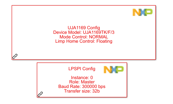
3)Although we operate the SBC in normal mode, we cannot get 5V output. We only get 3V3. We are using sbc_uja1169_s32k_config. Although we activate the V2/VEXT config section in the regulator section, we cannot get output from V2. What is the reason of this? Can you help us?
- 新着としてマーク
- ブックマーク
- 購読
- ミュート
- RSS フィードを購読する
- ハイライト
- 印刷
- 不適切なコンテンツを報告
I know this is now an old post, but I've cross posted and asked the model based design team to have a look here.
https://community.nxp.com/t5/Model-Based-Design-Toolbox-MBDT/RDDRONE-BMS771-MBDT-question/m-p/158619...
- 新着としてマーク
- ブックマーク
- 購読
- ミュート
- RSS フィードを購読する
- ハイライト
- 印刷
- 不適切なコンテンツを報告
Hi @OGUZ1,
Please see https://github.com/NXPHoverGames/RDDRONE-BMS772/ for the NuttX RDDRONE-BMS772 BMS example. Documentation, source code, binary and a manual can all be found at that website. It uses the POSIX compliant RTOS NuttX. That example contains the things like SSD1306 display support and configured SBC for 5V.
If Matlab/Simulink, FREEMASTER or something else is used to re-program the boards, there might be different software running on the microcontroller and thus it won't have the correct behavior and functions. You are free to re-program this board/microcontroller with the software you want (or make!), but make sure that what you program is what you are looking for.
If you would like to create your software, you could create it based on sources from https://github.com/NXPHoverGames/RDDRONE-BMS772/. This could help you get started with NXP components like the SBC (UJA1169), the BCC (MC33772B) or the NTAG5 boost NFC chip. If you want to program the NuttX BMS example, there is already a binary on that website/repository which you could easily program using the J-Link commander application (for windows (or JLinkExe on Linux)) and a J-Link programmer.
- 新着としてマーク
- ブックマーク
- 購読
- ミュート
- RSS フィードを購読する
- ハイライト
- 印刷
- 不適切なコンテンツを報告
I want to run the screen via Matlab/Simulink. Can you share any example with me? I can see the battery values with Matlab/Simulink. I want to use CAN communication but I still can't get 5V from SBC. I still could not get 5V output from SBC. Are you interested in me?
Best Regards!
- 新着としてマーク
- ブックマーク
- 購読
- ミュート
- RSS フィードを購読する
- ハイライト
- 印刷
- 不適切なコンテンツを報告
Hi @OGUZ1,
Sorry I do not have experience using MBDT in Matlab / Simulink.
For the help with the model based design toolbox and SBC 5V problems. @mariuslucianand could you help @OGUZ1 further with this?
It could be that the UJA1169 configuration might be meant only for the S32K144 evb board, which could be different than what should be used on the RDDRONE-BMS772.
For example, on the S32k144 evb LPSPI1 is used to communicate with the SBC.
While on the RDDRONE-BMS772 LPSPI0 is used.
Could you verify that the correct SPI bus 0 is used to communicate with the SBC?
According to @constantinrazva the SBC driver is located in the external devices.
Could you verify that you are using this SBC block?
If you are interested to see how to set the SBC using C code, here is an example: https://github.com/NXPHoverGames/RDDRONE-BMS772/blob/main/src/sbc.c
This enables the 5V in normal operation of the SBC.
For the display, we have example code how to use the display with the NuttX RTOS.
See https://github.com/NXPHoverGames/RDDRONE-BMS772/blob/main/src/display.c.
It uses the characters and drivers from this NuttX RTOS.
The display itself is a SSD1306 I2C display that works at both 5V and 3.3V.
I believe there are many C examples of how to work with this kind of display.
For example: https://github.com/adafruit/Adafruit_SSD1306
For MATLAB maybe these sources would be able to help as well: https://nl.mathworks.com/matlabcentral/fileexchange/50766-ssd1306-hex-bitmap-creator?s_tid=srchtitle or https://nl.mathworks.com/matlabcentral/answers/512483-how-to-control-ssd1306-128x32-oled-display-in-...
Kind regards and have a nice weekend,
Cis van Mierlo
- 新着としてマーク
- ブックマーク
- 購読
- ミュート
- RSS フィードを購読する
- ハイライト
- 印刷
- 不適切なコンテンツを報告
Hi, @cisvmierlo
Thank you very much for your reply.
Yes, I'm using SPI0 but I can't see any effect. I always read something like 2.7Volt from pin V2. I always read 3.3 volts from V1 pin. I still read the same values when I press the reset button. I couldn't figure out what it means. I tried all the configurations. Vbat and Wake pins are the same value in SBC.
When I press reset, the Wake pin drops to 0. 3.3 volts is always going to the SBCWake pin of the processor.
- 新着としてマーク
- ブックマーク
- 購読
- ミュート
- RSS フィードを購読する
- ハイライト
- 印刷
- 不適切なコンテンツを報告
Hi @OGUZ1,
I wanted to let you know that the RDDRONE-BMS772 board is now supported in the NXP Model-Based Design Toolbox (MBDT) for S32K1xx - version 4.3.0.
Here is the Product Release Announcement: https://community.nxp.com/t5/NXP-Model-Based-Design-Tools/NXP-Model-Based-Design-Toolbox-for-S32K1xx...
The NXP MBDT includes an integrated Simulink®-embedded target supporting NXP MCUs for direct rapid prototyping and built-in support for software- and processor-in-the-loop (SIL and PIL) development. https://www.nxp.com/design/automotive-software-and-tools/model-based-design-toolbox-mbdt:MBDT
Kind regards!
- 新着としてマーク
- ブックマーク
- 購読
- ミュート
- RSS フィードを購読する
- ハイライト
- 印刷
- 不適切なコンテンツを報告
Hi,
We want to use RDDRONE-BMS772 for solar drone with 20 Nos. of 4S battery packs in parallel. Please clarify the following queries,
1. Can RDDRONE-BMS772 board be used readily or any software to be uploaded before using?
2. Can we connect 20 nos. of BMS772 in parallel to charge 20 no. battery packs (each pack has 4S cells)? If yes, any additional protection to be provided externally?
3. Is there any inbuilt protection to prevent MOSFET failure in BMS772? If not, what happens to batteries when MOSFET fails?
4. Are external MOSFETs required for Active cell balancing? How active cell balance works in BMS772?
Thanks in advance.
- 新着としてマーク
- ブックマーク
- 購読
- ミュート
- RSS フィードを購読する
- ハイライト
- 印刷
- 不適切なコンテンツを報告
Hi @Prince1,
First of all, best wishes for this new year!
My apologies for the late response, we had some time off.
To answer your questions:
-
The BMS772 comes with pre-installed example software, but you might want to update it to the latest version. But keep in mind that it is a development platform with open source example software. This software is opensource and provided for development purposes and not warranted for end use. You will still need to ensure that the hardware and software meets your needs.
-
Currently we have not tested the BMS with multiple packs in parallel. It could be that the hardware could accommodate it, but the software and state machine would need to be reviewed for correct operation in parallel configuration.
-
There is a self-test build in which will test if the MOSFET can be switched off during startup. This to ensure the MOSFET and its control circuitry is fully functional and can be used for HW/SW OC/OV/temp protections (see SW release documentation). What happens to the batteries depend on the scenario, is it charging or discharging, does it need to connect or disconnect the batteries using the MOSFET. Plus the BMS is not the same as a battery charger. An externally controlled constant current (CC) constant voltage (CV) source is still required to charge the batteries.
-
Currently the BMS has on-board balance resistors plus FETs inside the installed BCC chip to balance the cells, a command from the MCU to the BCC enables or disables balancing for each individual cell.
I hope this answers your questions!