
- NXP Forums
- Product Forums
- General Purpose MicrocontrollersGeneral Purpose Microcontrollers
- i.MX Forumsi.MX Forums
- QorIQ Processing PlatformsQorIQ Processing Platforms
- Identification and SecurityIdentification and Security
- Power ManagementPower Management
- MCX Microcontrollers
- S32G
- S32K
- S32V
- MPC5xxx
- Other NXP Products
- Wireless Connectivity
- S12 / MagniV Microcontrollers
- Powertrain and Electrification Analog Drivers
- Sensors
- Vybrid Processors
- Digital Signal Controllers
- 8-bit Microcontrollers
- ColdFire/68K Microcontrollers and Processors
- PowerQUICC Processors
- OSBDM and TBDML
-
- Solution Forums
- Software Forums
- MCUXpresso Software and ToolsMCUXpresso Software and Tools
- CodeWarriorCodeWarrior
- MQX Software SolutionsMQX Software Solutions
- Model-Based Design Toolbox (MBDT)Model-Based Design Toolbox (MBDT)
- FreeMASTER
- eIQ Machine Learning Software
- Embedded Software and Tools Clinic
- S32 SDK
- S32 Design Studio
- Vigiles
- GUI Guider
- Zephyr Project
- Voice Technology
- Application Software Packs
- Secure Provisioning SDK (SPSDK)
- Processor Expert Software
-
- Topics
- Mobile Robotics - Drones and RoversMobile Robotics - Drones and Rovers
- NXP Training ContentNXP Training Content
- University ProgramsUniversity Programs
- Rapid IoT
- NXP Designs
- SafeAssure-Community
- OSS Security & Maintenance
- Using Our Community
-
-
- Home
- :
- QorIQ Processing Platforms
- :
- QorIQ
- :
- Re: Conflict between fm1dtsec1 and fm1dtsec4 in P5040DS-PB based target
Conflict between fm1dtsec1 and fm1dtsec4 in P5040DS-PB based target
- Subscribe to RSS Feed
- Mark Topic as New
- Mark Topic as Read
- Float this Topic for Current User
- Bookmark
- Subscribe
- Mute
- Printer Friendly Page
Conflict between fm1dtsec1 and fm1dtsec4 in P5040DS-PB based target
- Mark as New
- Bookmark
- Subscribe
- Mute
- Subscribe to RSS Feed
- Permalink
- Report Inappropriate Content
Hi ,
I am working on a custom target based on P5040DS-PB. The MDC/MDIO interface of the processor connects to two devices
1. Quad PHY
2. Ethernet Switch
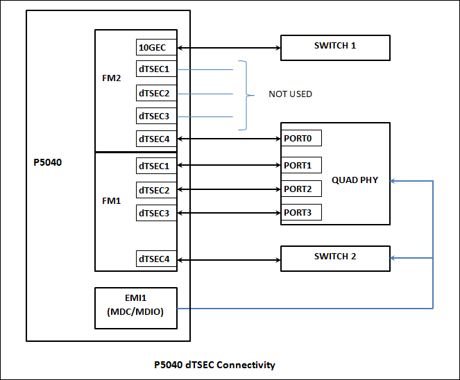
Four ports of the Quad PHY are connected to the following DTSEC interfaces of the Processor. FM1DTSEC1, FM1DTSEC2, FM1DTSEC3, FM2DTSEC4 having MDC/MDIO addresses 0x3, 0x2, 0x1, 0x4 respectivly.
The Ethernet Switch is connected on FM1DTSEC4 ( address 0x5 )
The problem is in reading the Ethernet Switch Id which is correctly read from U-boot and from the user space after OS boot-up, when device tree (p5040ds_1.dts) is used. Please note that in this device tree (p5040ds_1.dts) , FM1DTSEC1 is commented out to correctly read the Ethernet Switch Id using Processor MDC/MDIO.
Now on using the device tree (p5040ds_2.dts) , the Ethernet Switch Id read returns incorrect value on using the same Processor MDC/MDIO interface to read Ethernet Switch Id. Please note that in this case , the device tree (p5040ds_2.dts) has FM1DTESE1.
Please guide in locating the problem. I believe the problem should be in device tree configuration or something to do with FM1DTSEC1.
Note :: To read Ethernet Switch Id from user space , "bus" is exported in the kernel. The same "bus" is used to read the Ethernet Switch Id from user space after the OS boot-up.
Thanks
Ram
Original Attachment has been moved to: p5040ds_2.dts.zip
Original Attachment has been moved to: p5040ds_1.dts.zip
- Mark as New
- Bookmark
- Subscribe
- Mute
- Subscribe to RSS Feed
- Permalink
- Report Inappropriate Content
Hi ufedor,
Please refer the attached dts files. The reg value of mdio0: is 0x5 instead of 0x3. Apologies for the inconvenience.
The switch in question is Marvell 88E6097. To read the switch Id, kernel source file "phy_device.c" is modified to accommodate the Switch read which is at address 0x5. A function(marvell_get_switch_id) to read switch Id is added in "phy_device.c".
On correct reading of switch id , bus->read returns 0x992 , else it returns 0x16d.
- Mark as New
- Bookmark
- Subscribe
- Mute
- Subscribe to RSS Feed
- Permalink
- Report Inappropriate Content
- Mark as New
- Bookmark
- Subscribe
- Mute
- Subscribe to RSS Feed
- Permalink
- Report Inappropriate Content
Please find target boot log and corresponding dts attached herewith.
Please note that in the Boot log file Card_BootLog.txt (before kernel prompt) , there are two MDC/MDIO reads for address 0x5. One using bus Freescale PowerQUICC MII Bus and other using mdio_mux.
Switch Id read is OK with the bus Freescale Power QUICC MII Bus and it is not OK with the bus mdio_mux.
After boot-up , from the user space on trying to read the same Switch Id , using the same bus , i.e. Freescale Power QUICC MII Bus, Switch Id read is NOT OK. The same may be referred in the attached log (Card_BootLog.txt).
Please suggest.
Thanks
Ram
- Mark as New
- Bookmark
- Subscribe
- Mute
- Subscribe to RSS Feed
- Permalink
- Report Inappropriate Content
Hi ,
What should be the correct entry in dts so that both FM1DTSEC1(Quad Phy addr 0x3) and FM1DTSEC4 ( Switch Addr 0x5) are correctly addressed using MDC/MDIO.
Thanks
Ram
- Mark as New
- Bookmark
- Subscribe
- Mute
- Subscribe to RSS Feed
- Permalink
- Report Inappropriate Content
> Ethernet Switch Id which is correctly read from U-boot
Sorry, I can't find this in the provided log.
- Mark as New
- Bookmark
- Subscribe
- Mute
- Subscribe to RSS Feed
- Permalink
- Report Inappropriate Content
- Mark as New
- Bookmark
- Subscribe
- Mute
- Subscribe to RSS Feed
- Permalink
- Report Inappropriate Content
In the provided p5040ds_testing.dts:
mdio0: mdio@e1120 {
tbi0: tbi-phy@5 {
reg = <0x5>;
device_type = "tbi-phy";
and
mdio-mux-emi1 {
compatible = "mdio-mux-mmioreg", "mdio-mux";
mdio-parent-bus = <&mdio0>;
#address-cells = <1>;
#size-cells = <0>;
reg = <9 1>; // BRDCFG1
mux-mask = <0x78>; // EMI1
/*
* Virtual MDIO for the four-port SGMII cards.
*/
hydra_sg_slot2: sgmii-mdio@28 {
reg = <0x28>; /* EMI1_EN | 0x20 */
#address-cells = <1>;
#size-cells = <0>;
phy_sgmii_slot2_1: ethernet-phy@1 {
reg = <0x1>;
};
phy_sgmii_slot2_2: ethernet-phy@2 {
reg = <0x2>;
};
phy_sgmii_slot2_3: ethernet-phy@3 {
reg = <0x3>;
};
phy_sgmii_slot2_4: ethernet-phy@4 {
reg = <0x4>;
};
phy_sgmii_slot2_5: ethernet-phy@5 {
reg = <0x5>;
Please note that external MII Management interface (EMI1) uses MDIO-1 for EMAC1.
This means that PHY ID 0x5 can't be used as internal TBY PHY id and as external PHY id in this case.
- Mark as New
- Bookmark
- Subscribe
- Mute
- Subscribe to RSS Feed
- Permalink
- Report Inappropriate Content
>>This means that PHY ID 0x5 can't be used as internal TBY PHY id and as external PHY id in this case
Does it mean that PHY ID 0x5 should be used as external PHY in this case ?
Please give your input on how should I go about changing the dts source in addition to any relevant documents that should be referred for the required changes.
Thanks
Ram
- Mark as New
- Bookmark
- Subscribe
- Mute
- Subscribe to RSS Feed
- Permalink
- Report Inappropriate Content
> Does it mean that PHY ID 0x5 should be used as external PHY in this case ?
Exactly.
For example use 0x6 for internal TBI PHY of the FM1DTSEC1.
- Mark as New
- Bookmark
- Subscribe
- Mute
- Subscribe to RSS Feed
- Permalink
- Report Inappropriate Content
Hi ,
Is it the correct dts configuration for using addr 0x3 for internal TBI PHY of FM1DTSEC1 ?
mdio0: mdio@e1120 {
tbi0: tbi-phy@3 {
reg = <0x3>;
device_type = "tbi-phy";
Further, what entry into dts is to be added for addr 0x5 for external PHY of FM1DTSEC4?
Please guide.
Regards
Ram
- Mark as New
- Bookmark
- Subscribe
- Mute
- Subscribe to RSS Feed
- Permalink
- Report Inappropriate Content
This is not correct.
The TBI PHY ID of the FM1DTSEC1 must differ from all external PHYs IDs connected to the mdio0.
- Mark as New
- Bookmark
- Subscribe
- Mute
- Subscribe to RSS Feed
- Permalink
- Report Inappropriate Content
Hi,
Now all the TBI PHY addresses are different ( PHY addr 0x8 ) from the external PHY addresses (0x1, 0x2, 0x3, 0x4, 0x5 ). The corresponding dts entry is made accordingly. However, the issue remain same, i.e. on reading the Marvell Switch Id (Addr 0x5) , it is giving incorrect value (0x16d) instead of the correct value (0x992).
Am I missing something in the dts or using a wrong dts entry.
Regards
Ram
- Mark as New
- Bookmark
- Subscribe
- Mute
- Subscribe to RSS Feed
- Permalink
- Report Inappropriate Content
You wrote:
> it is giving incorrect value (0x16d) instead of the correct value (0x992).
How this corresponds with the provided "Card_UbootLog.txt"?
Please provide the processor DTSECs and MII Management interface connection block diagram.
- Mark as New
- Bookmark
- Subscribe
- Mute
- Subscribe to RSS Feed
- Permalink
- Report Inappropriate Content
>>How this corresponds with the provided "Card_UbootLog.txt"?
The attached Log file is "Card_Log-1.txt" in my previous reply. Last line is the Switch Id read value from user space.
>>Please provide the processor DTSECs and MII Management interface connection block diagram
I will update the same very soon.
- Mark as New
- Bookmark
- Subscribe
- Mute
- Subscribe to RSS Feed
- Permalink
- Report Inappropriate Content
>>How this corresponds with the provided "Card_UbootLog.txt"?
From the u-boot , Switch Id read using MDC/MDIO is OK (0x992). However the issue is after the OS boot-up the Switch Id read is incorrect.
- Mark as New
- Bookmark
- Subscribe
- Mute
- Subscribe to RSS Feed
- Permalink
- Report Inappropriate Content
> the Ethernet Switch Id which is correctly read from U-boot
Which log corresponds to this statement?
Card_UbootLog.txt
- Mark as New
- Bookmark
- Subscribe
- Mute
- Subscribe to RSS Feed
- Permalink
- Report Inappropriate Content
Hi,
PFA processor DTSECs and MII Management interface connection block diagram.
> the Ethernet Switch Id which is correctly read from U-boot
Which log corresponds to this statement?
Hope I have made my point clear to you on this question. The following line in the Card_UbootLog.txt is relevant for the Switch Id read which is obtained by using the mii info command in u-boot promtp -
PHY 0x05: OUI = 0x0099, Model = 0x99, Rev = 0x02, 1000baseX, FDX
- Mark as New
- Bookmark
- Subscribe
- Mute
- Subscribe to RSS Feed
- Permalink
- Report Inappropriate Content
From the "Card_Log-1.txt":
MURMU :: of_mdio_parse_addr addr 0x4
get_phy_device for phyAddr 0x4
MURMU :: within get_phy_device for addr 0x4
*****MURMU :: add 0x4 Bus name mdio_mux
MURMU :: R
MURMU :: mux_read BUS_NUM 0x28
MURMU :: R1 0x4
read 600d from addr 4/2
MURMU :: R
MURMU :: mux_read BUS_NUM 0x28
MURMU :: R1 0x4
read 8463 from addr 4/3
Registering PHY DEVICE addr 0x4, phyID = 0x600d8463
MURMU :: of_mdiobus_register_phy addr 0x4
MURMU :: of_mdio_parse_addr addr 0x5
get_phy_device for phyAddr 0x5
MURMU :: within get_phy_device for addr 0x5
*****MURMU :: add 0x5 Bus name mdio_mux
M D :: bus->name mdio_mux
MURMU :: W
MURMU :: mux_write BUS_NUM 0x28
MURMU :: W1 mid 0x5 reg 0x0 val 0x9a03
WR RV 0x0
MURMU :: R
MURMU :: mux_read BUS_NUM 0x28
MURMU :: R1 0x5
read 016d from addr 5/1
RD DAT 0x16d
MURMU :: ****** mdiobus_marv_switch_read val 0x16d
Registering PHY DEVICE addr 0x5, phyID = 0x16d0000
Why different registers are read for PHYs 0x4 and 0x5?
- Mark as New
- Bookmark
- Subscribe
- Mute
- Subscribe to RSS Feed
- Permalink
- Report Inappropriate Content
>Why different registers are read for PHYs 0x4 and 0x5?
PHY4 is a port of QUAD PHY that supports direct addressing of IEEE clause 22 registers. PHY identifier register is at register address 0x2 and 0x3.
PHY5 is for Marvell Switch that supports indirect addressing, i.e. all other switch registers are accessed via two directly accessible registers by clause 22 MDC/MDIO , command register (0x0) and data register (0x1).
- Mark as New
- Bookmark
- Subscribe
- Mute
- Subscribe to RSS Feed
- Permalink
- Report Inappropriate Content
Thank you for the explanation.
Just a sanity check - why 'emi1' mdio is located inside the 'board-control' branch? Is the multiplexer really implemented?