
- NXP Forums
- Product Forums
- General Purpose MicrocontrollersGeneral Purpose Microcontrollers
- i.MX Forumsi.MX Forums
- QorIQ Processing PlatformsQorIQ Processing Platforms
- Identification and SecurityIdentification and Security
- Power ManagementPower Management
- MCX Microcontrollers
- S32G
- S32K
- S32V
- MPC5xxx
- Other NXP Products
- Wireless Connectivity
- S12 / MagniV Microcontrollers
- Powertrain and Electrification Analog Drivers
- Sensors
- Vybrid Processors
- Digital Signal Controllers
- 8-bit Microcontrollers
- ColdFire/68K Microcontrollers and Processors
- PowerQUICC Processors
- OSBDM and TBDML
-
- Solution Forums
- Software Forums
- MCUXpresso Software and ToolsMCUXpresso Software and Tools
- CodeWarriorCodeWarrior
- MQX Software SolutionsMQX Software Solutions
- Model-Based Design Toolbox (MBDT)Model-Based Design Toolbox (MBDT)
- FreeMASTER
- eIQ Machine Learning Software
- Embedded Software and Tools Clinic
- S32 SDK
- S32 Design Studio
- Vigiles
- GUI Guider
- Zephyr Project
- Voice Technology
- Application Software Packs
- Secure Provisioning SDK (SPSDK)
- Processor Expert Software
-
- Topics
- Mobile Robotics - Drones and RoversMobile Robotics - Drones and Rovers
- NXP Training ContentNXP Training Content
- University ProgramsUniversity Programs
- Rapid IoT
- NXP Designs
- SafeAssure-Community
- OSS Security & Maintenance
- Using Our Community
-
-
- Home
- :
- Power Management
- :
- Power Management
- :
- Re: NXQ1TXH5, breakage possible ?
NXQ1TXH5, breakage possible ?
- Subscribe to RSS Feed
- Mark Topic as New
- Mark Topic as Read
- Float this Topic for Current User
- Bookmark
- Subscribe
- Mute
- Printer Friendly Page
NXQ1TXH5, breakage possible ?
- Mark as New
- Bookmark
- Subscribe
- Mute
- Subscribe to RSS Feed
- Permalink
- Report Inappropriate Content
Hello NXP,
We have a non starting NXQ1TXH5 here and suspect a breakage that we try to understand.
In our schematics, a led in serie with a resistor, is supplied by 5V(from USB supply) and goes into LED_R pin.
The rest of the NXQ (VSYS) is supplied by a 5V, coming from a backuped supply.
The resistor , limiting led current limits to ~7mA , so does it in LED_R pin , at maximum.
Except this led input, the rest of the schematic is identical to UM10943 eval board.
Question:
Is it possible that : the 5VUSB coming up earlier than the backuped one breaks the component because datasheet says that voltage on inputs like LED_R should be <VDD , which is is =0 when VUSB comes up.
Isn't the internal transistor on LED_R blocked until VDD is up on the NXQ ? Clamping diodes here ?
Thanks for your help.
Yann
- Mark as New
- Bookmark
- Subscribe
- Mute
- Subscribe to RSS Feed
- Permalink
- Report Inappropriate Content
The non starting was due to a pcb issue . Solved.
I have a question: the ping signal is different than the one you sent attached which is equal to the one I see with the eval board.
It appears with every small glitch (~0.529s) when I have the coil wired and every ~4s when the coil is not wired (like eval board).
Is it normal ? It makes me think that it detects something at every small glitch and tries to start. Which is not normal as there is nothing in front of the coil.
Thanks for your help.
- Mark as New
- Bookmark
- Subscribe
- Mute
- Subscribe to RSS Feed
- Permalink
- Report Inappropriate Content
Thank you Jozef,
i have no activity on output 1&2.
Neither on the CNF_IN pin where I should see the measurement every ~3s.
But at the same time i have no activity on the quartz. In this case i believe that the chip is unable to do anything, right ?
I'm investigating this.
In case we do not wire a coil: is the chip trying to ping as you mentionned ?
- Mark as New
- Bookmark
- Subscribe
- Mute
- Subscribe to RSS Feed
- Permalink
- Report Inappropriate Content
Hello Yann,
please see a reply from an application engineer I have contacted.
DESCRIPTION
I don't think that the connection of he LED breaks down the NXQ1TXH5.
They should measure the voltage on OUT1 and OUT2 without a receiver placed and then they should
see the ping signal there switching between 0V and 5V. Please see a scope attached.
If there is no signal at all or only on one of the two, then the internal mosfets are broken
and too high voltage is supplied.
Then they should investigate if there backupend supply is working correctly: the voltage
should always remain below 5V.
They also should not submit the charger coil to a magnetic field.
With Best Regards,
Jozef
- Mark as New
- Bookmark
- Subscribe
- Mute
- Subscribe to RSS Feed
- Permalink
- Report Inappropriate Content
Thank you Jozef,
i have no activity on output 1&2.
Neither on the CNF_IN pin where I should see the measurement every ~3s.
But at the same time i have no activity on the quartz. In this case i believe that the chip is unable to do anything, right ?
I'm investigating this.
In case we do not wire a coil: is the chip trying to ping as you mentionned ?
- Mark as New
- Bookmark
- Subscribe
- Mute
- Subscribe to RSS Feed
- Permalink
- Report Inappropriate Content
Hello Ysellin,
please see below a reply from the application engineer.
DESCRIPTION
When nothing is placed on the charger coil, then he signal on OUT1/OUT2 should look like this:
every 400msec there is an "analog ping" (small glitch) and every 4 seconds there is a "digital ping" (thick glitch).
analog-digital ping.jpg
During the analog ping the full bridge in the NXQ1TXH5 is switching a few times and then the current is monitored.
When there is an object (coin, telephone, something from metal) on the charger coil then the current ringing is strongly damped.
This is detected and the NXQ1TXH5 then starts a digital ping in order to find out if the "object" is sending messages back.
object on the charger.png
In the picture below the NXQ1TXH5 is every analog ping detecting an "object" and starts a digital ping. However it does not get
any response and then goes to sleep again till the next analog ping.
detecting an object.jpg
If the above picture is measured without an object on the charger coil (or other metal in the vicinity of the coil), then the resistance of the charger coil is too high.
With Best Regards,
Jozef
- Mark as New
- Bookmark
- Subscribe
- Mute
- Subscribe to RSS Feed
- Permalink
- Report Inappropriate Content
Thank you Jozef.
I have a constant detection of something that leads to digital ping every 0.5s .
What is the best way to find the cause ? I already have set FOD_E and R8 and R14 according to "NXQ1TXH5-FOD Configuration" document.
Remains FOD-T parameter which will be difficult to set because our mechanical stack leads certainly to a bit more loss in the path.
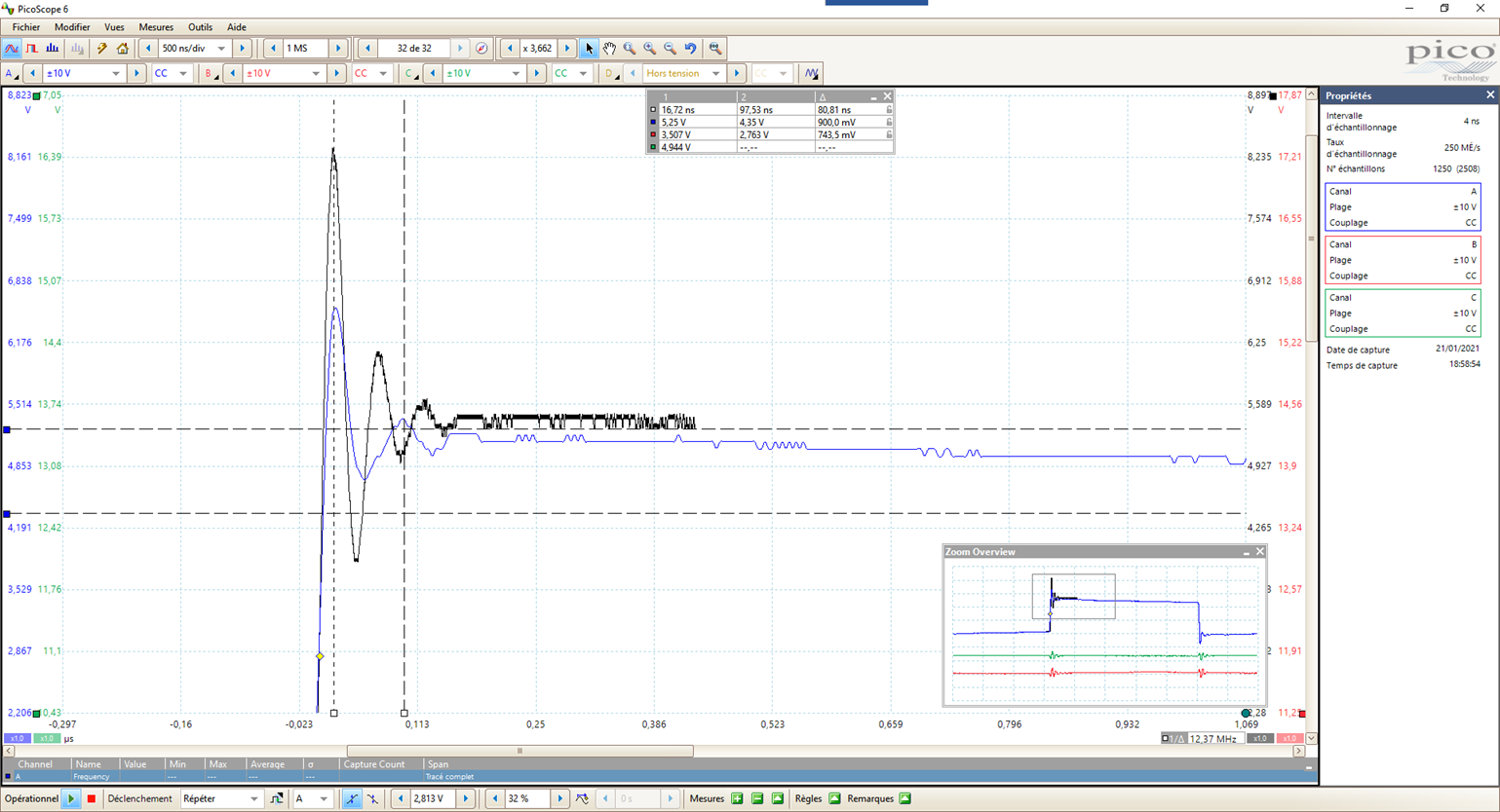
Snubber : seeing the attached curve "snubber..." where black trace is original snubber (6.8nF) and bleu trace with 16nF, do you think that we should add more capacitance ?
- Mark as New
- Bookmark
- Subscribe
- Mute
- Subscribe to RSS Feed
- Permalink
- Report Inappropriate Content
Hello Ysellin,
could you please reattach the "snubber" file you mentioned? It seems it didn't pass.
With Best Regards,
Jozef
- Mark as New
- Bookmark
- Subscribe
- Mute
- Subscribe to RSS Feed
- Permalink
- Report Inappropriate Content

- Mark as New
- Bookmark
- Subscribe
- Mute
- Subscribe to RSS Feed
- Permalink
- Report Inappropriate Content
Hello Ysellin,
please see below an answer from the application engineer.
DESCRIPTION
The best way to find the rootcause is to remove all metal objects in the vicinity of the charger coil and see if the problem
persists. If the problem persists, then the resistance in the LC tank is too high.
Which charger coil is the customer using? It should be a 6.3uH / Qi A11 coil.
They can connect one of the coils attached, and see if the problems is gone.
With Best Regards,
Jozef
- Mark as New
- Bookmark
- Subscribe
- Mute
- Subscribe to RSS Feed
- Permalink
- Report Inappropriate Content
Hello, Jozef,
we use a different coil due to shape of the product where an A11 would be too big.
Furthermore we do not need Qi compliance/certificate and product will be precisely located by mechanical parts.
Coil is Wurth 760308102308.
It has 30mR resistance and 3µH impedance.
It is compensated by using 760nF capacitor to keep the frequency at ~100kHz.
The coil 760308111 has indeed a lower DCRes, 20-25mR.
can the 10mR extra DCRes be the cause of these constant "analog detection". Is there a way to compensate it with any resistor on the device ?
- Mark as New
- Bookmark
- Subscribe
- Mute
- Subscribe to RSS Feed
- Permalink
- Report Inappropriate Content
- Mark as New
- Bookmark
- Subscribe
- Mute
- Subscribe to RSS Feed
- Permalink
- Report Inappropriate Content
Thank you for that advice.
The A11 coils are way too big for our product.
If we use a coil with 6.8 µH but with 340mR it leads to R/L = 50000
This should fit , right ?
At the end of your message "...soon be another problem" => what does he/she have in mind ?
- Mark as New
- Bookmark
- Subscribe
- Mute
- Subscribe to RSS Feed
- Permalink
- Report Inappropriate Content
Hi Ysellin,
please see an answer from the application engineer.
DESCRIPTION
They can try and see if it solves the ping issue, but I stand by my previous statement:
The charger is not a standalone circuit with just a coil + capacitor: at the moment a receiver is
placed the charger coil is the primary winding of a resonant converter. So also the number of turns
from the charger coil is important as well as the size of the coil and coupling between charger coil
and receiver coil.
With Best Regards,
Jozef