
- Forums
- Product Forums
- General Purpose MicrocontrollersGeneral Purpose Microcontrollers
- i.MX Forumsi.MX Forums
- QorIQ Processing PlatformsQorIQ Processing Platforms
- Identification and SecurityIdentification and Security
- Power ManagementPower Management
- Wireless ConnectivityWireless Connectivity
- RFID / NFCRFID / NFC
- Advanced AnalogAdvanced Analog
- Neural Processing UnitsNeural Processing Units
- MCX Microcontrollers
- S32G
- S32K
- S32V
- MPC5xxx
- Other NXP Products
- S12 / MagniV Microcontrollers
- Powertrain and Electrification Analog Drivers
- Sensors
- Vybrid Processors
- Digital Signal Controllers
- 8-bit Microcontrollers
- ColdFire/68K Microcontrollers and Processors
- PowerQUICC Processors
- OSBDM and TBDML
- S32M
- S32Z/E
-
- Solution Forums
- Software Forums
- MCUXpresso Software and ToolsMCUXpresso Software and Tools
- CodeWarriorCodeWarrior
- MQX Software SolutionsMQX Software Solutions
- Model-Based Design Toolbox (MBDT)Model-Based Design Toolbox (MBDT)
- FreeMASTER
- eIQ Machine Learning Software
- Embedded Software and Tools Clinic
- S32 SDK
- S32 Design Studio
- GUI Guider
- Zephyr Project
- Voice Technology
- Application Software Packs
- Secure Provisioning SDK (SPSDK)
- Processor Expert Software
- Generative AI & LLMs
-
- Topics
- Mobile Robotics - Drones and RoversMobile Robotics - Drones and Rovers
- NXP Training ContentNXP Training Content
- University ProgramsUniversity Programs
- Rapid IoT
- NXP Designs
- SafeAssure-Community
- OSS Security & Maintenance
- Using Our Community
-
- Cloud Lab Forums
-
- Knowledge Bases
- ARM Microcontrollers
- i.MX Processors
- Identification and Security
- Model-Based Design Toolbox (MBDT)
- QorIQ Processing Platforms
- S32 Automotive Processing Platform
- Wireless Connectivity
- CodeWarrior
- MCUXpresso Suite of Software and Tools
- MQX Software Solutions
- RFID / NFC
- Advanced Analog
- Neural Processing Units
-
- NXP Tech Blogs
- RSS フィードを購読する
- トピックを新着としてマーク
- トピックを既読としてマーク
- このトピックを現在のユーザーにフロートします
- ブックマーク
- 購読
- ミュート
- 印刷用ページ
PCF2129 time errors
- 新着としてマーク
- ブックマーク
- 購読
- ミュート
- RSS フィードを購読する
- ハイライト
- 印刷
- 不適切なコンテンツを報告
I am using a PCF2129 with a S08QE micro controller communicating via I2C. The circuit is exactly the same as the example in the data sheet and application note. Battery backup is supplied by a 3V button cell. All settings ar default values and the only initialisation is to clear any interrupt flags (writing 00 to Control Register 2). Software is created using Codewarrior V11.1 and communication is achieved through the I2C component of ProcessorExpert at 400Khz. We have 20 samples and everything works correctly - The controller can read and display the time, which can set via application software.
When the systems are powered up some of the units display the wrong time. The number of "faulty" units varies between 3 and 8 and they are NOT the same units each time and the "actual incorrect times" also varies each time. The batteries are all new. After the incorrect time is corrected the units all function correctly until the power is re-cycled (MAYBE!!!!!).
- 新着としてマーク
- ブックマーク
- 購読
- ミュート
- RSS フィードを購読する
- ハイライト
- 印刷
- 不適切なコンテンツを報告
I am getting rather despondent. We still have between 10% and 20% of devices losing time between power off and power on. I have tried every one of your suggestions - but to no avail. We monitored the alarm registers. We made a note of the contents of the alarm registers, switched off, waited about one hour and switched on. Of those that showed the wrong time we checked the alarm registers - they were all correct.
- 新着としてマーク
- ブックマーク
- 購読
- ミュート
- RSS フィードを購読する
- ハイライト
- 印刷
- 不適切なコンテンツを報告
Hi Julian,
I see you have posted another question a week ago, but in my PC it was updated only now with your second message. I didn't see your first message a week ago. I apologize for that, its a system issue. I don't have any other idea what could cause the time lose. I have contacted an application engineer dealing with RTCs for an advice. As soon as I will receive an answer from him I will definitely reply to you.
Thank you for your patience.
With Best Regards,
Jozef
- 新着としてマーク
- ブックマーク
- 購読
- ミュート
- RSS フィードを購読する
- ハイライト
- 印刷
- 不適切なコンテンツを報告
Hi Julian,
I still haven't received an answer from the application engineer. As soon as I will receive an answer from him I will definitely reply to you.
Thank you for your patience.
With Best Regards,
Jozef
- 新着としてマーク
- ブックマーク
- 購読
- ミュート
- RSS フィードを購読する
- ハイライト
- 印刷
- 不適切なコンテンツを報告
Hi Julian,
I have checked your schematic again and I am missing the bulk capacitor on the VDD pin. Please refer to the Figure 48. in the PCF2129 datasheet. Because the direct switch to battery helped to diminish the issue, I suspect that without the 6.8uF bulk capacitor the internal operating voltage drops too low causing the oscillator to stop temporarily in some cases. Please try to add the 6.8uF capacitor on the VDD pin, which might hold the internal operating voltage at proper value during the battery switching.

With Best Regards,
Jozef
- 新着としてマーク
- ブックマーク
- 購読
- ミュート
- RSS フィードを購読する
- ハイライト
- 印刷
- 不適切なコンテンツを報告
Hi Julian,
I apologize for sending you another update. I am reading an AN11186, because of another case, and in section 5.3 an RC network on the VDD pin is recommended. Please check it an if the 6.8uF bulk capacitor doesn't help, please try to add the 330Ohm resistor.

With Best Regards,
Jozef
- 新着としてマーク
- ブックマーク
- 購読
- ミュート
- RSS フィードを購読する
- ハイライト
- 印刷
- 不適切なコンテンツを報告
Latest update.
Of the 20 units on test - 2 lost time (let us assume for the purpose of this report that it was one hour late). This time we did not correct the time, but carried on with the power cycling test. They continued displaying the "correct" time, but one hour late. With a production of several thousand units this is still a problem.
- 新着としてマーク
- ブックマーク
- 購読
- ミュート
- RSS フィードを購読する
- ハイライト
- 印刷
- 不適切なコンテンツを報告
Dear Julian,
I presume the time error occurs on the devices where the battery switch happens second time. Please refer to section 8.11.4 and Table 71. in the PCF2129 datasheet. If the battery switch occurs for the first time, the time and date are stored in the timestamp registers, because the BF bit in the Control_3 register is set to 0 by default, but after the battery switch occurs, the BF bit is set to logic 1 and in the next battery switch the timestamp registers are not modified.
Please set the BF bit to logic 0 after the battery switch occurs. This should solve the issue with time errors.

Please also check this example code from Tomas in this link.
With Best Regards,
Jozef
- 新着としてマーク
- ブックマーク
- 購読
- ミュート
- RSS フィードを購読する
- ハイライト
- 印刷
- 不適切なコンテンツを報告
THank you for this information. I have not yet had an opportunity to test it, but I hope you can explain something.
I understand what the timestamp registers are for, but how does this affect the contents of the time registers. Why should they change when all the timestamp registers do is to record the time at which an event occurred?
- 新着としてマーク
- ブックマーク
- 購読
- ミュート
- RSS フィードを購読する
- ハイライト
- 印刷
- 不適切なコンテンツを報告
Dear Julian,
you are right. I posted my answer too hastily. The timestamp registers will most probably not affect the time registers. Could you please check the section 8.8.8 in the PCF2129 datasheet? Could you please confirm, that the all accesses are completed within one second? Also is the reading access made in one go?


Could you please test the Tomas's code and see if it solves the issue?
With Best Regards,
Jozef
- 新着としてマーク
- ブックマーク
- 購読
- ミュート
- RSS フィードを購読する
- ハイライト
- 印刷
- 不適切なコンテンツを報告
All accesses are made in one go. I only read seconds, minutes and hours and I do not use the seconds information, but I read the time every half second.This is not really necessary - i just make use of an existing timing loop - which I can easyily extend.. Also it would appear that the consequence of section 8.8.8 are a roll-over whereas my problem can show difference of several hours. To illustrate this - in one example at 08:00 the units were switched on and one unis showed 15:27
- 新着としてマーク
- ブックマーク
- 購読
- ミュート
- RSS フィードを購読する
- ハイライト
- 印刷
- 不適切なコンテンツを報告
Dear Julian,
The functionality of the battery switch-over is limited by the fact that the power supply VDD is monitored every 1 ms in order to save power consumption. Considering that the battery switch-over threshold value (Vth(sw)bat) is typically 2.5 V, the power management operating limit (VDD(min)) is 1.8 V and that VDD is monitored every 1 ms, the battery switch-over works properly in cases where VDD falls with a rate lower than 0.7 V/ms. Could you please provide oscilloscope waveform of VDD, VBAT and CLKOUT during the VDD switchover event?
What are the settings for COF[2:0] and PWRMNG[2:0] bits?
Please share your schematic with voltage levels and part values.
With Best Regards,
Jozef
- 新着としてマーク
- ブックマーク
- 購読
- ミュート
- RSS フィードを購読する
- ハイライト
- 印刷
- 不適切なコンテンツを報告
COF[2:0] is 000 (default)
PWRMNG[2:0]] is 000 (default)
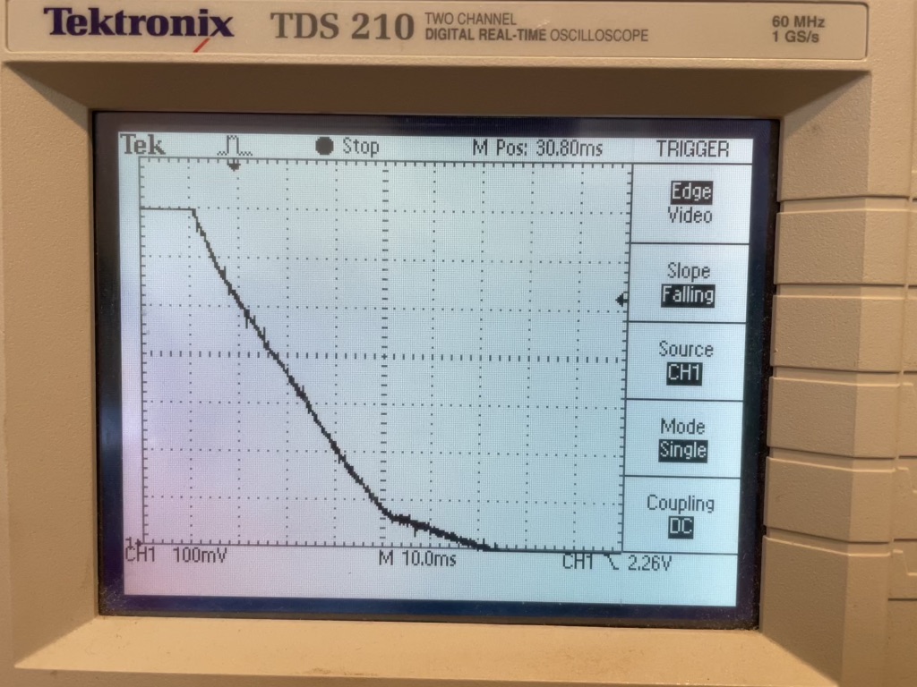
Waveform A shows the initial voltage drop which is 0.64V in 40ms giving a rate of 16mV/ms. The display is 100mv/cm and 10ms/cm
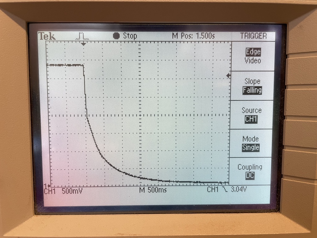
Waveform B shows the whole supply voltage decay. The display is 0.5V/cm and 500ms/cm.
The discontinuity (shown clearer in waveform A) can be attributed to the shutting down of the LED display (7 off 7-segment digits)
The battery voltage remains constant at 3.0V throughout.
Regarding the schematic, Vcc is 3.3V, V_Batt is 3.0V and R9 and R10 have been changed to 1K8
- 新着としてマーク
- ブックマーク
- 購読
- ミュート
- RSS フィードを購読する
- ハイライト
- 印刷
- 不適切なコンテンツを報告
SORRY, I forgot to mention, I cannot get any useful measurement from CLKOUT as it is an open drain and nothing is connected to it.
- 新着としてマーク
- ブックマーク
- 購読
- ミュート
- RSS フィードを購読する
- ハイライト
- 印刷
- 不適切なコンテンツを報告
Dear Julian,
thank you for the schematic and the scopes. So the too high fall rate is not the reason. 16mV/ms is way lower, than 700mV/ms.
I have two suggestions. Please test them.
1. Please disable the CLKOUT output by the COF[2:0] bits in the CLKOUT register, address 0Fh. This probably will not help, but please test it.


2. This suggestion might solve your issue. How are set the PWRMNG [2:0] bits in the Control_3 register, address 02h? Are they left default?

Please set to bits to 011 to direct switching mode, so the internal operating voltage doesn't drop to Vth(sw)bat, but switches to VBAT supply when the VDD < VBAT.


With Best Regards,
Jozef
- 新着としてマーク
- ブックマーク
- 購読
- ミュート
- RSS フィードを購読する
- ハイライト
- 印刷
- 不適切なコンテンツを報告
Thank you for the suggestions - I will try them. I have been reluctant to try the Direct Mode because VDD is 3.3V and VBATT is 3.0V.
- 新着としてマーク
- ブックマーク
- 購読
- ミュート
- RSS フィードを購読する
- ハイライト
- 印刷
- 不適切なコンテンツを報告
Dear Julian,
ok. Hopefully it will solve the issue.
With Best Regards,
Jozef
- 新着としてマーク
- ブックマーク
- 購読
- ミュート
- RSS フィードを購読する
- ハイライト
- 印刷
- 不適切なコンテンツを報告
I am starting to get somewhat despondent. We have tried all recommendations and we are still getting approximately 10% failures. I am fairly convinced that the time registers are being corrupted when the unit is switched off. The unit is a time and temperature controlled (hence the clock chip) 150W heater. The heater is switched by the micro controller via a zero-crossing OPTO coupler and a TRIAC. We are testing 20 110V units - all fed from a local 220/110V transformer, but we don't know if the interference is caused on the board or via the transformer. the random factors are: -
When power is removed from the board, is the heater ON , OFF or switching?
When power is removed from the board, is the I2C in the process of transferring data?