
- NXP Forums
- Product Forums
- General Purpose MicrocontrollersGeneral Purpose Microcontrollers
- i.MX Forumsi.MX Forums
- QorIQ Processing PlatformsQorIQ Processing Platforms
- Identification and SecurityIdentification and Security
- Power ManagementPower Management
- MCX Microcontrollers
- S32G
- S32K
- S32V
- MPC5xxx
- Other NXP Products
- Wireless Connectivity
- S12 / MagniV Microcontrollers
- Powertrain and Electrification Analog Drivers
- Sensors
- Vybrid Processors
- Digital Signal Controllers
- 8-bit Microcontrollers
- ColdFire/68K Microcontrollers and Processors
- PowerQUICC Processors
- OSBDM and TBDML
-
- Solution Forums
- Software Forums
- MCUXpresso Software and ToolsMCUXpresso Software and Tools
- CodeWarriorCodeWarrior
- MQX Software SolutionsMQX Software Solutions
- Model-Based Design Toolbox (MBDT)Model-Based Design Toolbox (MBDT)
- FreeMASTER
- eIQ Machine Learning Software
- Embedded Software and Tools Clinic
- S32 SDK
- S32 Design Studio
- Vigiles
- GUI Guider
- Zephyr Project
- Voice Technology
- Application Software Packs
- Secure Provisioning SDK (SPSDK)
- Processor Expert Software
-
- Topics
- Mobile Robotics - Drones and RoversMobile Robotics - Drones and Rovers
- NXP Training ContentNXP Training Content
- University ProgramsUniversity Programs
- Rapid IoT
- NXP Designs
- SafeAssure-Community
- OSS Security & Maintenance
- Using Our Community
-
-
- Home
- :
- Product Forums
- :
- Other NXP Products
- :
- NXQ1TXH5 keeps shutting down with error
NXQ1TXH5 keeps shutting down with error
- Subscribe to RSS Feed
- Mark Topic as New
- Mark Topic as Read
- Float this Topic for Current User
- Bookmark
- Subscribe
- Mute
- Printer Friendly Page
NXQ1TXH5 keeps shutting down with error
- Mark as New
- Bookmark
- Subscribe
- Mute
- Subscribe to RSS Feed
- Permalink
- Report Inappropriate Content
Hello,
I have used the NXQ1TXH5 qi wireless charger IC in a project. The deviceis powered by lipo batteries and the board also includes a BQ24075 battery management IC and TPS61230 Boost converter IC. The issue we're having is that when I place my phone on the coil for charging, it charges for some time and then cuts off with the LED_R led blinking continuously. Also this error is very inconsistent i.e. it doesn't have a fixed time interval before it cuts off or at sometimes it just works and continues to work without hiccups.
This is the coil that I'm using : https://www.mouser.com/datasheet/2/400/lc_tx_wt505090-10k2-a11-g_en-1150025.pdf
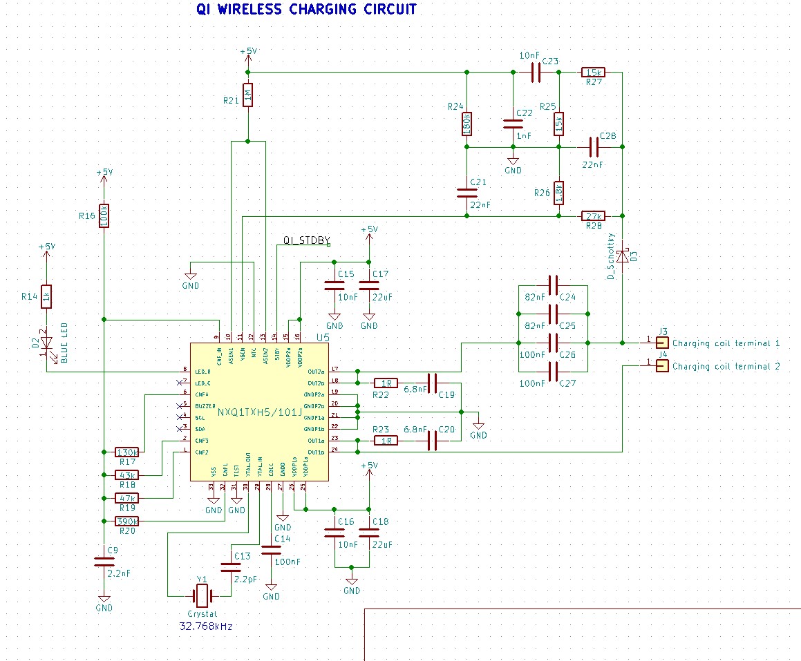
I'm using literally the same circuit as used in the NXQ1TXH5DB1401 demo board. LED mode 11 is being used.
Fixed errors:
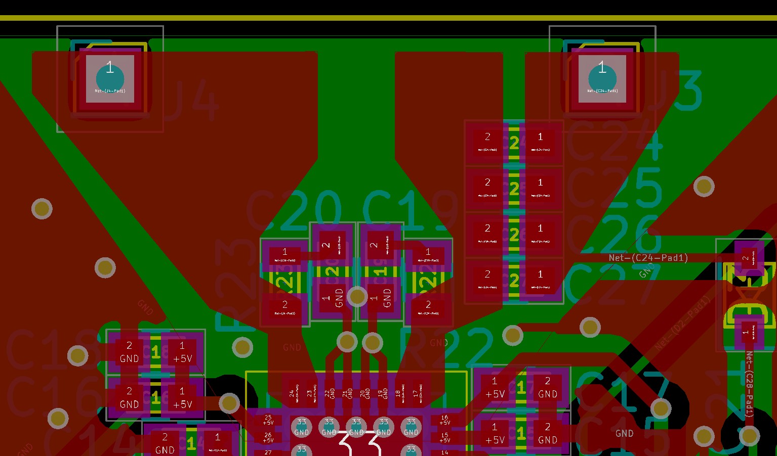
1) R16 value is wrong in the schematic. Please ignore this error as it has been replaced to the correct value of 390kΩ on the board.
2) R24, C22 and C23 are supposed to be connected to the ASEN1 and ASEN2 pins according to the datasheet. Please ignore this error in the schematic and the layout as it has been corrected physically using a jumper wire on the board itself.
We just purchased the NXQ1TXH5DB1355 debugger to get the error codes. In the meanwhile could someone tell me if there's anything wrong in the schematics, layouts (apart from the two known errors mentioned above) and help in figuring out this error.
- Mark as New
- Bookmark
- Subscribe
- Mute
- Subscribe to RSS Feed
- Permalink
- Report Inappropriate Content
Hello Avinash,
First, please accept my apologies for the delayed response.
Regarding the issue that you are presenting, it can be caused by OverTemperature protection (OTP) that the NXQ1TXH5/101 has. When the IC temperatures exceed 110 °C, the output power is stopped and, when the junction temperature drops below 80°C, will resume the operation. To know when this protection is triggered, the LED will blink. This OTP will be always active even though the NTC pin is connected to ground to disable the built-in temperature reduction mechanism; this will ensure safe device operation. You can find more details on section 2.1.4 of the application note AN11775. In the same application note in section 5, you can see the layout guidelines including thermal layout specification that will help to keep the IC as cool as possible for proper operation.
I hope this information can be helpful.
Have a great day,
Paulina
-------------------------------------------------------------------------------
Note:
- If this post answers your question, please click the "Mark Correct" button. Thank you!
- We are following threads for 7 weeks after the last post, later replies are ignored
Please open a new thread and refer to the closed one, if you have a related question at a later point in time.
-------------------------------------------------------------------------------