
- NXP Forums
- Product Forums
- General Purpose MicrocontrollersGeneral Purpose Microcontrollers
- i.MX Forumsi.MX Forums
- QorIQ Processing PlatformsQorIQ Processing Platforms
- Identification and SecurityIdentification and Security
- Power ManagementPower Management
- MCX Microcontrollers
- S32G
- S32K
- S32V
- MPC5xxx
- Other NXP Products
- Wireless Connectivity
- S12 / MagniV Microcontrollers
- Powertrain and Electrification Analog Drivers
- Sensors
- Vybrid Processors
- Digital Signal Controllers
- 8-bit Microcontrollers
- ColdFire/68K Microcontrollers and Processors
- PowerQUICC Processors
- OSBDM and TBDML
-
- Solution Forums
- Software Forums
- MCUXpresso Software and ToolsMCUXpresso Software and Tools
- CodeWarriorCodeWarrior
- MQX Software SolutionsMQX Software Solutions
- Model-Based Design Toolbox (MBDT)Model-Based Design Toolbox (MBDT)
- FreeMASTER
- eIQ Machine Learning Software
- Embedded Software and Tools Clinic
- S32 SDK
- S32 Design Studio
- Vigiles
- GUI Guider
- Zephyr Project
- Voice Technology
- Application Software Packs
- Secure Provisioning SDK (SPSDK)
- Processor Expert Software
-
- Topics
- Mobile Robotics - Drones and RoversMobile Robotics - Drones and Rovers
- NXP Training ContentNXP Training Content
- University ProgramsUniversity Programs
- Rapid IoT
- NXP Designs
- SafeAssure-Community
- OSS Security & Maintenance
- Using Our Community
-
-
- Home
- :
- Product Forums
- :
- Other NXP Products
- :
- Current measurement using MM9Z1J638BM2EP Chip
Current measurement using MM9Z1J638BM2EP Chip
- Subscribe to RSS Feed
- Mark Topic as New
- Mark Topic as Read
- Float this Topic for Current User
- Bookmark
- Subscribe
- Mute
- Printer Friendly Page
Current measurement using MM9Z1J638BM2EP Chip
- Mark as New
- Bookmark
- Subscribe
- Mute
- Subscribe to RSS Feed
- Permalink
- Report Inappropriate Content
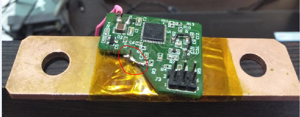
In our custom board previously we got 400 mA in no load condition.Now we placed PCB very close to shunt and we are measuring around 80-90mA of no load current..In our hardware shunt leads are not exactly mounted to the PCB test points.Below we have attached the snap of our hardware.We are following KTRD9Z1-638-12VUG as reference.
1.What is the minimum current which we can be measure through 100uOhms shunt
2.What is the effect of placing the PCB near to the shunt.
3.What happens if the shunt leads does not match PCB test points.
4.Can we measure 1mA or less in no load condition with our hardware .
Please suggest us to do any modification on our hardware to measure minimum current in no load condition.
- Mark as New
- Bookmark
- Subscribe
- Mute
- Subscribe to RSS Feed
- Permalink
- Report Inappropriate Content
Let me try to answer your questions:
1.What is the minimum current which we can be measure through 100uOhms shunt
In principle you can measure with a resolution of 1mA. The reachable accuracy is 0.5% gain error plus 0.5uV offset error. So at 0A is should be in the range of ~+/- 5mA (0.1uV = 1mA with 100uOhm shunt). One further aspect is that there is quite an amount of random noise added to each individual measurement result, therefore you should evaluate the measurements using averaging over multiple results (for accuracy evaluations on ISENSE I recommend something like 1000 values). E.g. with ADC settings DEC=512, IIR=1/32 and I=0A => gain256 the noise is ~1.07uVrms or ~10.7mArms. Assuming a typical spread individual results can vary by 3*rms => ~+/-30mA.
Note: To reach the full accuracy a calibration on system level is required, which eliminates errors introduced by e.g. soldering.
2.What is the effect of placing the PCB near to the shunt.
3.What happens if the shunt leads does not match PCB test points.
The proximity/distance is not immediately introducing an measurement error. (I used a shunt connected with 2 twisted 25cm long wires without issues "on my desk"). The errors are introduced by coupling noise and by unintentional currents flowing. Remember that 100uOhm is a pretty small resistance and 0.1uV (= 1mA) is a small signal. So I would state that a careful layout is most important and proximity is important in particular under EMI conditions.
4.Can we measure 1mA or less in no load condition with our hardware .
See above.
Please suggest us to do any modification on our hardware to measure minimum current in no load condition.
The 400mA and 80-90mA seems to big! There a multiple sources for errors, like schematics, layout, software.I suggest the following steps:
- check that one side of the shunt is referenced to AGND

- measurements at 3 different currents, e.g. 1A, 0A, -1A (averaged results N=1000)
- schematics and layout review
You can also send me emails directly!
- Mark as New
- Bookmark
- Subscribe
- Mute
- Subscribe to RSS Feed
- Permalink
- Report Inappropriate Content
How the calibration in system level is done .Do we have any fixed procedure for calibration.
- Mark as New
- Bookmark
- Subscribe
- Mute
- Subscribe to RSS Feed
- Permalink
- Report Inappropriate Content
Thanks for clarification.We need some more support on this issue .Please share your mail id.